Manuals
/
Brands
/
Computer Equipment
/
Laptop
/
Aspire Digital
/
Computer Equipment
/
Laptop
Aspire Digital
5534
- page 128
1
128
224
224
Download
224 pages, 10.4 Mb
118
Chapter 3
Replacing the Mainboard
1.
Connect the DC-In Cable to the mainboard.
2.
Reach under the mainboard to plug in the LVDS cable.
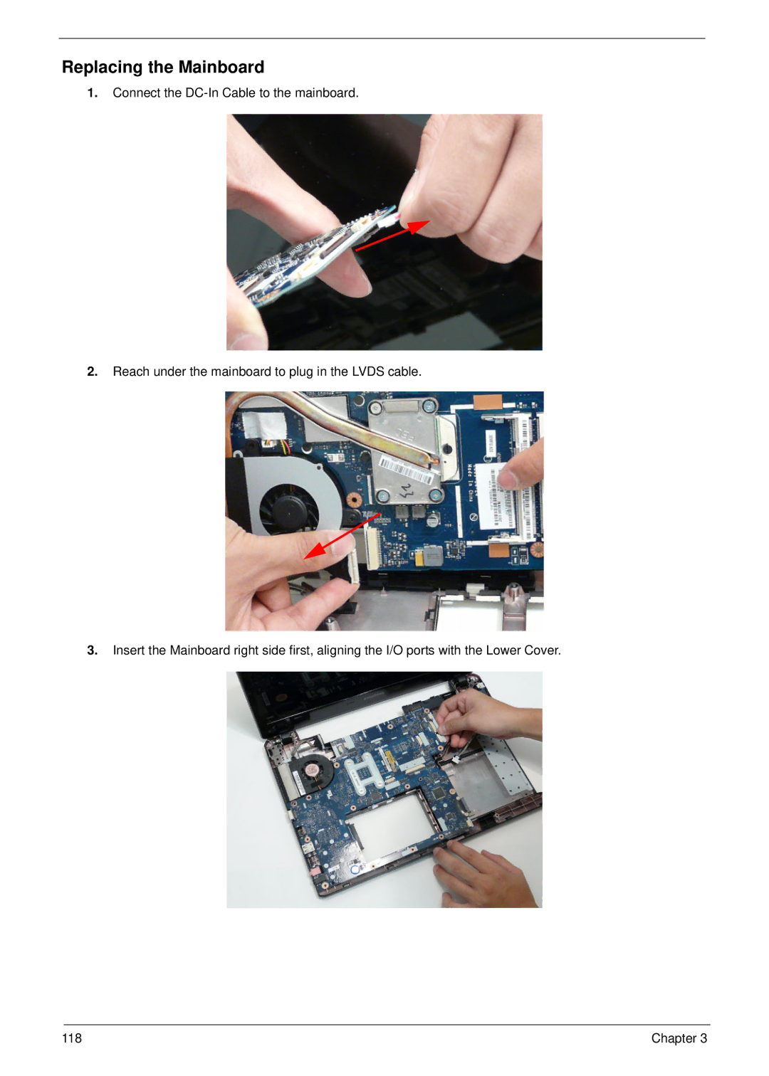
3.
Insert the Mainboard right side first, aligning the I/O ports with the Lower Cover.
Contents
Main
Page
Copyright
Disclaimer
Conventions
Preface
Page
System Specifications 1
System Utilities 23
Machine Disassembly and Replacement 43
43
Page
Troubleshooting 148
Jumper and Connector Locations 173
FRU (Field Replaceable Unit) List 177
Model Definition and Configuration 188 Test Compatible Components 206
Online Support Information 210 Index 211
Page
System Specifications
Chapter 1
Features
Privacy control
Dimensions and Weight
Power subsystem
Special keys and controls
I/O interface
System Block Diagram
ENE KB926
AMD S1G1 Processor
ATI RS780MN
ATI SB710
Your Notebook Tour
Front View
Closed Front View
Left View
Right View
Base View
Rear View
Indicators
TouchPad Basics
Using the Keyboard
Lock Keys and embedded numeric keypad
Windows Keys
Hot Keys
Special Keys
Hardware Specifications and Configurations
Page
Page
Page
Page
Page
Page
Page
Page
System Utilities
Chapter 2
BIOS Setup Utility
Navigating the BIOS Utility
Information
Main
Advanced
Page
Security
Page
Page
Power
Boot
Exit
Page
DOS Flash Utility
Page
Remove HDD/BIOS Password Utilities
Page
Miscellaneous Utilities
Using Boot Sequence Selector
Using DMITools
Example 1: Read DMI Information from Memory
Example 2: Write Product Name to EEPROM
Using the LAN MAC Utility
Page
Page
Machine Disassembly and Replacement
Chapter 3
Disassembly Requirements
Related Information
General Information
Pre-disassembly Instructions
Disassembly Process
Chapter 3 45
External Module Disassembly Process
External Modules Disassembly Flowchart
Screw List
Page
Page
Page
Page
Page
Page
Page
Page
Page
Page
Page
Page
58 Chapter 3
Main Unit Disassembly Process
Main Unit Disassembly Flowchart
Screw List
Page
Removing the Keyboard
Page
Page
Page
Page
Page
Removing the Button Board
Page
Removing the Touchpad Bracket
Page
Removing the Power Board
Page
Removing the Speaker Modules
Page
Page
Page
Page
Page
Page
Page
Page
Page
Page
Page
Page
Page
Page
Page
Page
Page
LCD Module Disassembly Process
LCD Module Disassembly Flowchart
Page
Page
Page
Page
Page
Page
Page
Page
Page
Page
Page
Page
Page
Page
Page
Page
Page
Page
Page
Page
Page
Page
Page
Replacing the Thermal Module
Page
Page
Page
Page
Page
Page
Page
Page
Page
Page
Page
Page
Replacing the Power Board
Page
Page
Page
Page
Page
Page
Page
Page
Page
Page
Page
Page
Page
Page
Page
Page
Page
Page
Page
Page
Troubleshooting
Chapter 4
Common Problems
Power On Issue
Computer Shutsdown Intermittently
No Display Issue
No POST or Video
Abnormal Video Display
Random Loss of BIOS Settings
Page
Page
Sound Problems
Internal Microphone Failure
Microphone Problems
HDD Not Operating Correctly
ODD Failure
ODD Not Operating Correctly
Discs Do Not Play
Discs Do Not Burn Properly
Playback is Choppy
Drive Not Detected
Drive Read Failure
Page
161 Chapter 4
Wireless Function Failure
Chapter 4 162
Bluetooth Function Failure
Easy Button Failure
163 Chapter 4
Thermal Unit Failure
External Mouse Failure
Other Failures
Intermittent Problems
Undetermined Problems
POST Code Tables
Sec
Memory
DLL Timing Control Registers, RCOMP settings
BDS & Specific action:
Each PEIM entry point used in 80_PORT
Page
Page
Page
Page
Jumper and Connector Locations
Chapter 5
Top View
Bottom View
Clearing Password Check and BIOS Recovery
Clearing Password Check
Hardware Open Gap Description
Steps for Clearing BIOS Password Check
BIOS Recovery by Crisis Disk
BIOS Recovery Boot Block:
BIOS Recovery Hotkey:
Steps for BIOS Recovery from USB Storage:
FRU (Field Replaceable Unit) List
Chapter 6
Aspire 5534 Exploded Diagrams
Main Assembly
LCD Assembly
Aspire 5534 FRU List
Page
Page
Page
Page
Page
Screw List
Page
Appendix A 188
Model Definition and Configuration
Appendix A
Aspire 5534
189 Appendix A
Appendix A 190
191 Appendix A
Appendix A 192
193 Appendix A
Appendix A 194
195 Appendix A
Appendix A 196
Model Acer Part No Memory 3Memory
4HDD 1(GB) HDD 2(GB) ODD
197 Appendix A
Model Acer Part No Memory 3Memory
Appendix A 198
Model Acer Part No Memory 3Memory
199 Appendix A
Model Acer Part No Memory 3Memory
Appendix A 200
201 Appendix A
Appendix A 202
203 Appendix A
Appendix A 204
205 Appendix A
Page
Windows 7 Environment Test
Page
Page
Online Support Information
Appendix C
Index
A
B
C
D
J
K
L
M
N
U
V
W