English
Copyright Notice
Disclaimer
30.5cm
English Motherboard Layout
LAN Port LED Indications
Panel
Off No Link Blinking
Link
Table for Audio Output Connection
Introduction
Package Contents
English Specifications
Rear Panel I/O
Audio
Bios Features
Connectors
USB3.0
Ports, supports USB 1.1/2.0/3.0 up to 5Gb/s
Support CD
Unique Features
Hardware
Monitor
English
English
English
English
Screw Holes
Pre-installation Precautions
Step Orient the CPU with the IHS Inte
CPU Installation
Grated Heat Sink up. Locate Pin1
Two orientation key notches
English
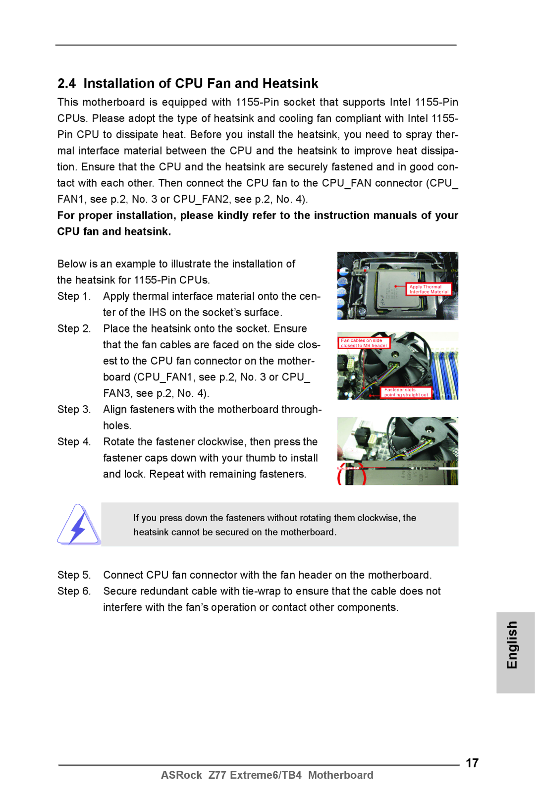
Installation of CPU Fan and Heatsink
Dual Channel Memory Configuration
English Installation of Memory Modules Dimm
Installing a Dimm
English Expansion Slots PCI and PCI Express Slots
Installing an expansion card
Requirements
Slitm and Quad Slitm Operation Guide
ASRock SLIBridge2S Card
Double-click Nvidia Settings icon on your Windows taskbar
Driver Installation and Setup
For Windows XP / XP 64-bit OS For Slitm mode only
Select Control Panel tab
Select Nvidia Control Panel tab
CrossFireXTM and Quad CrossFireXTM Operation Guide
Installing Two CrossFireXTM-Ready Graphics Cards
CrossFire Bridge
For Windows XP OS
Install the required drivers to your system
For Windows 8 / 7 / VistaTM OS
AMD Catalyst Control Center
English
Internal VGA
Thunderbolt
Sub port Hdmi port
Dual Monitor and Surround Display
Dual Monitor
For Windows XP / XP 64-bit OS
Surround Display Feature
Hdcp
What is HDCP?
Install the Multi-Angle CIR Receiver to the front USB port
ASRock Smart Remote Installation Guide
Make sure the option CIR Controller is set to Enabled
Advanced Super IO Configuration CIR Controller Enabled
CIR sensors in different angles
Jumper
Jumpers Setup
Description
Clear Cmos Jumper
Onboard Headers and Connectors
Optional wireless transmitting
USB 3.0 Header Besides four default USB
Connect the remote controller
Ports on the I/O panel, there is
Functions
System Panel Header
Several system front panel
English
ATX 12V Power Connector Please connect an ATX
ATX Power Connector
One Ieee 1394 header on this
Port on the I/O panel, there is
Motherboard. This Ieee
Header can support one Ieee
Smart Switches
Status Code Description
15 Dr. Debug
English
English
English
Install Windows XP / XP 64-bit OS on your system
\ RAID Installation Guide
English
Bios Information
Deutsch
Kartoninhalt
Spezifikationen
Anschlüsse
64Mb AMIs Legal Bios Uefi mit GUI-Unterstützung
Rücksetzschalter Reset mit LED
Audioeingang / Lautsprecher vorne / Mikrofon
Sata 3-Anschlüsse 6,0 Gb/s durch Intel Z77
Zertifizierungen
CD d’assistance
Hardware Monitor
Cmos löschen
Einstellung der Jumper
Jumper Einstellun Beschreibung
Integrierte Header und Anschlüsse
USB 2.0-Ports an den
USB 2.0-Header
Anschlüssen befinden sich
Drei USB 2.0- Anschlussleisten
Ermöglicht Ihnen eine bequeme
Seite Ihres Gehäuses
Anschlussmöglichkeit und
Kontrolle über Audio-Geräte
Gehäuselautsprecher an
Gehäuselautsprecher-Header Schließen Sie den
Diesen Header an
Betriebs-LED-Header Bitte schließen Sie die
Gehäuse und Strom lüfteranschlüsse
Pins 1-3 anschließen
ATX-Netz-Header Verbinden Sie die ATX
Stromversorgung mit diesem
SLI/XFIRE-Stromanschluss
ATX 12V Anschluss
IEEE-1394 Port auf dem Ein
IEEE-1394 Header Außer einem vorgegebenem
Ausgabe Paneel, gibt es einen
IEEE-1394 Header
Schnellschalter
BIOS-Information
Français
Contenu du paquet
Chipsets
Format
Mémoire
Slot d’extension
Port souris/clavier PS/2 Port D-Sub Port Hdmi
Panneau arrière
Connecteurs
USB
Système
Surveillance
Effacer la Cmos
Le cavalier Description
Ces quatre connecteurs Série
Connecteurs Série ATA2
ATA2 SATA2 prennent en
Charge les câbles Sata pour
Il y a trois embases USB
En-tête USB
Sur cette carte mère. Chaque
Embase USB 2.0 peut prendre
Permet le branchement et le
Connecteur audio panneau ’est une interface pour un
Contrôle commodes de
Périphériques audio
En-tête
En-tête du haut-parleur Veuillez connecter le De châssis
LED di accensione Collegare il LED di accensione
Chassi per indicare lo stato di
Tête
En-tête d’alimentation ATX Veuillez connecter l’unité
Connecteur ATX
Header de Ieee Sauf un port de default Ieee
Sur le panel I/O, il y a un
Header de IEEE1394
Un module de port COM
En-tête de port COM Cette en-tête de port COM est
Fournissant une sortie audio
Spdif vers la carte VGA Hdmi
Interrupteur rapides
Informations sur le Bios Informations sur le CD de support
Italiano
Contenuto della confezione
Specifiche
Posteriore I/O
Pannello
Driver, Utilità, Software AntiVirus versione di prova
Connettori
CD di
Monitoraggio
Supporto
Compatibilità
Certificazioni
Jumper Settaggio del Jumper
Setup dei Jumpers
Resettare la Cmos
Cavi dati Serial ATA Sata
Collettori e Connettori su Scheda
Connettori Serial ATA2
Predefinite nel pannello I/O, la
Collettore USB Oltre alle due porte USB
Scheda madre dispone di tre
Intestazioni USB 2.0. Ciascuna
Pannello frontale Pannello audio. Che consente
Connettore audio sul
Dei dispositivi audio
Collettore pannello di sistema
Collettore casse telaio Collegare le casse del telaio a
Reset interruttore di ripristino
Questo collettore
Pled LED alimentazione del sistema
Connettore
Connettore alimentazione ATX Collegare la sorgente
A questo connettore
Connettore ATX 12 Collegare un alimentatore ATX
4Connettore alimentazione SLI/XFIRE
Ieee 1394 sul pannello I/O, e‘
Utilizzato per supportare il
Collettore porta COM Questo collettore porta COM è
Modulo porta COM
Header Hdmispdif Header HDMISPDIF, con
Interruttori rapidi
Informazioni sul Bios Software di supporto e informazioni su
Placa base ASRock Z77 Extreme6/TB4
Contenido de la caja
Español
Español Especificación
Panel Trasero
Conectores
64Mb AMI Bios legal Uefi AMI compatible con GUI
Certificaciones
CD de soport
Jumper Setting
Setup de Jumpers
100
Limpiar Cmos
101
Cabezales y Conectores en Placas
102
Conveniente de apparatos de
103
Audio
Cabezal de panel de sistema
104
Conectores de ventilador de chasis / alimentación
105
Cabezal de alimentación ATX
Conecte la fuente de alimentación ATX a su cabezal
106
107
108
Conmutadores rápidos
109
Bios Información Información de Software Support CD
110
Комплектность
Русский
111
Спецификации
112
113
Операцион
114
Ные системы
Сертификаты
Перемычка Установка Описание
Установка перемычек
115
116
Колодки и разъемы на плате
117
118
119
Reset кнопка сброса
Pwrbtn кнопка питания
Pled индикатор питания системы
Контакты 1-3 подключены
120
121
122
123
Быстрое переключение
124
Информация о Bios
125
Paket İçindekiler
Türkçe
126
Özellikler
Arka Panel
127
Ses
128
Bios Özelliği
Konektör
Destek CD’si
Donanım
129
Monitör
Sertifikalar
130
Jumperların Ayarı
Jumper Ayar
CMOS’u temizleme
131
Yerleşik Fişler ve Konektörler
132
Işlevini barındırır
133
Sistem Paneli Fişi
134
ATX Güç Konektörü Lütfen bir ATX güç kaynağını
135
Bu konektöre bağlayın
ATX 12V Güç Konektörü
136
137
Akıllı Anahtarlar
138
Bios Bilgileri Yazılım Destek CD’si bilgileri
차폐 1 개 ASRock SLI 브릿지 2S 카드 1 개
139
140
141
142
전압 감시 기능 +12V,+5V,+3.3V,Vcore
143
마이크로 소프트 Windows 8 / 8 64 비트 / 7 / 7 64 비트
VistaTM / VistaTM 64 비트 / XP / XP 64 비트 와 호환
Cmos 초기화
144
시리얼 Atasata
145
SATA2 / SATA3 하드 디스크
혹은 SATA2 / SATA3 커넥터
USB 3.0 헤더
146
USB 2.0 헤더
오디오 인터페이스 입니다
147
CHAFAN2 및 CHAFAN3 은
148
S1/S3 상태에서는 LED 가 계속
CPU 팬 케이블을 이 커넥터에 연결하고 흑색 선을 접지 핀에맞 추십시오
149
150
151
152
빠른 스위치
153
시스템 바이오스 정보 소프트웨어 지원 CD 정보
ATX フォームファクター 12.0-in x 9.6-in, 30.5 cm x 24.4 cm
154
シリアル ATA Sata データケーブル(オプション)
I/O パネルシールド ASRock SLIBridge2S カード
155
156
157
ルチ調整 サポート CD
158
ルバー モニター CPU/ シャーシ温度検知 CPU/ シャーシ / 電源ファンタコメータ
自動調整が可能)
159
ジャンパ設定
160
オンボードのヘッダとコネクタ類
USB 3.0 ヘッダ
161
162
シャーシスピーカーヘッダ
CPU ファンコネクタ
164
てください。
165
166
クイックスイッヱ
このマザーボードは Microsoft Windows 8 / 8 64-bit / 7 / 7 64-bit
167
一個華擎 SLIBridge2S 橋接卡
168
ATX 規格 12.0 英吋 X 9.6 英吋 , 30.5 厘米 X 24.4 厘米
169
支持 Hyper-Threading 超線程技術
支持 Intel Extreme Memory ProfileXMP1.3/1.2
170
171
支持 ErP/EuP 需要同時使用支持 ErP/EuP 的電源供應器
172
清除 Cmos
173
174
175
機箱喇叭接頭
176
系統面板接頭
CHAFAN1, CHAFAN2 和
177
CHAFAN3 支持風扇控制。
CPU 風扇接頭
接頭。
178
到這個接頭。
除了位於 I/O 面板的一個默認
串行接口連接器
179
口的外設。
投影儀 / 液晶顯示器等設備。
180
快速開關
本主板支持各種微軟視窗操作系統:Microsoft Windows 8/8 64 位元 /7/7 64 位元
181
182
電子信息產品污染控制標示
一張華擎 SLIBridge2S 卡
183
ATX 規格 12.0 英吋 x 9.6 英吋 , 30.5 公分 x 24.4 公分
184
185
186
支援 ErP/EuP 需要同時使用支援 ErP/EuP 的電源供應器
187
VistaTM 64 位元 /XP/XP 64 位元
188
USB 2.0 擴充接頭
189
除了位於 I/O 面板的四個 USB
190
接口之外,這款主機板有一
紅外線模組接頭
啟鍵等各種連線。
191
電源指示燈接頭
192
ATX 電源接頭
193
請將 ATX 電源供應器連接到這個 接頭。
請將 ATX 12V 電源供應器連接到 這個接頭。
接口連接到這個接頭。
194
埠的裝置。
195
196
支援光碟訊息
Bahasa Indonesia
Isi Paket
197
198
Diagram
Podium
Grup Chip
Papan Belakang
199
Penghubung
Ciri-ciri Bios
200
Sokongan CD
201
Penjaga
Sertifikasi
202
Installing OS on a HDD Larger Than 2TB
Bit ..\i386\Win7VistaIntel Bit ..\AMD64\Win7-64Vista64Intel
Installing OS on a HDD Larger Than 2TB in RAID Mode
203
Windows VistaTM 64-bit
204
205
Windows 7 64-bit
206