Motherboard
E2126 First Edition July
Contents
Chapter Bios Setup
Federal Communications Commission Statement
Canadian Department of Communications Statement
Electrical safety
Operation safety
How this guide is organized
Where to find more information
Conventions used in this guide
A7N8X-XE Specifications Summary
Support CD
Page
Introduction
Special features
Package contents
Welcome
Serial ATA technology
Integrated 10/100 LAN controller
Coaxial S/PDIF out
USB 2.0 technology
Innovative Asus features
Before you proceed
Motherboard overview
Motherboard layout
Placement direction
Screw holes
Central Processing Unit CPU
Installing the CPU
Overview
Memory configurations
System memory
Recommended memory configurations
DDR400 Qualified Vendors List
SS/DS
Installing a Dimm
Removing a Dimm
Expansion slots
Installing an expansion card
2 Configuring an expansion card
Standard interrupt assignments
IRQ assignments for this motherboard
AGP slot
PCI slots
Jumpers
Clear RTC RAM Clrtc
PS2/USB Device Wake-up 3-pin PS2USBPW
A7N8X-XE PS2/USB Device Wake-up
Rear panel connectors
Connectors
Audio 2, 4, or 6-channel configuration
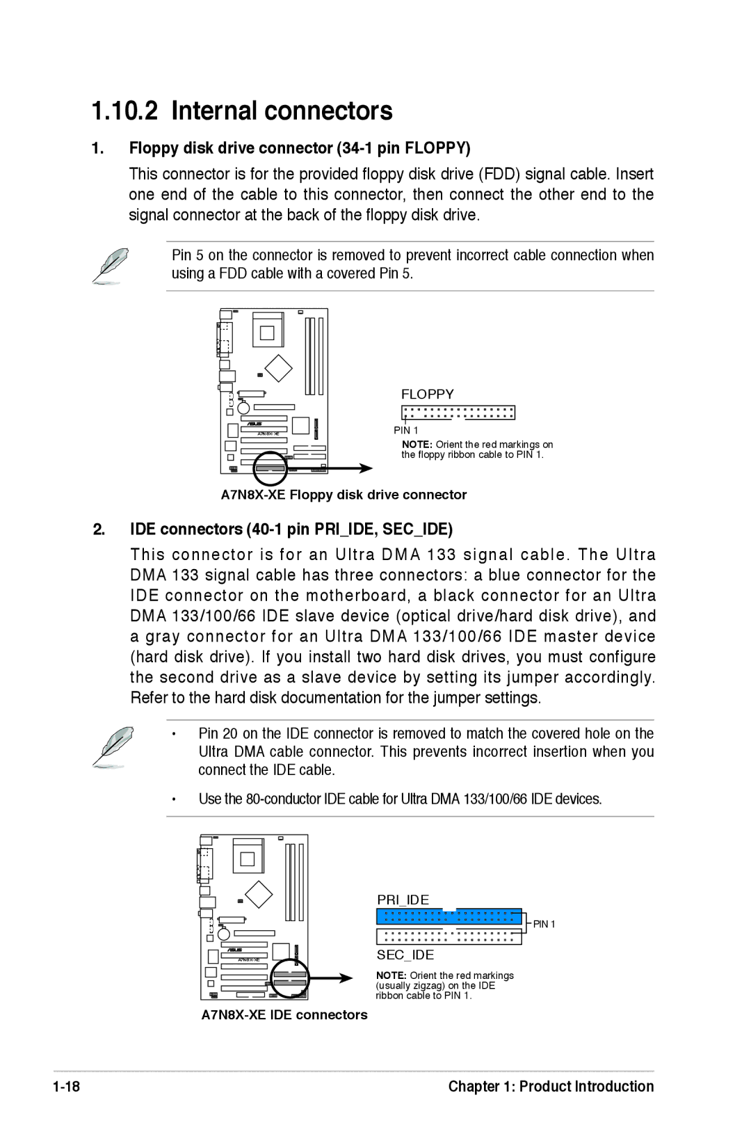
Floppy disk drive connector 34-1 pin Floppy
Internal connectors
IDE connectors 40-1 pin PRIIDE, Secide
Serial ATA connectors 7-pin SATA1, SATA2
CPU and chassis fan connectors 3-pin CPUFAN, Chafan
USB connectors 10-1 pin USB56, USB78
Internal audio connectors 4-pin CD, AUX
Front panel audio connectors 10-1 pin Fpaudio
ATX power connector 20-pin Atxpwr
System panel connector 20-pin Panel
System power LED 3-1 pin Pled
Reset button 2-pin Reset
ATX power button/soft-off button 2-pin Pwrbtn
Bios Setup
Managing and updating your Bios
Creating a bootable floppy disk
Using Afudos to update the Bios
Using Afudos to copy the current Bios
Afudos /ofilename
Afudos /i filename.rom
Asus CrashFree Bios utility
Using Asus EZ Flash to update the Bios
To update the Bios using Asus EZ Flash
Installing Asus Update
Asus Update utility
Updating the Bios through the Internet
Updating the Bios through a Bios file
Bios setup program
Flash ROM
Bios menu bar
Navigation keys
Tab
F10
Saving changes and exiting the Setup program
General help
Scroll bar
Sub-menu
Legacy Diskette B Disabled
Main menu
System Time hhmmss
System Date day, mm dd yyyy
LBA/Large Mode Auto
Type Auto
Block Multi-sector Transfer M Auto
Type Auto
System Information
Bios Setup Utility
JumperFree Configuration
AI Overclock Tuner Auto
JumperFree Configuration
USB Controller Enabled
USB 2.0 Support Enabled
USB Configuration
Legacy USB Support Auto
CPU Internal Cache Disabled
CPU Configuration
Chipset
NorthBridge Configuration
MDA Access Control PCI
TV Mode Support Default
C1 Discounnect Auto Mode
NorthBridge Chipset Configuration
System Performance Settings
Memory Clock Auto
Dram Timing Auto
Tras
Onboard LAN Enabled
MAC Bridge Mode Auto
OnBoard Sata Controller Enabled
Sata Operation Mode non-RAID
Onboard Devices Configuration
PCIPnP
Power menu
Suspend Mode Auto
Acpi Apic Support Enabled
Repost Video on S3 Resume No
APM Configuration
PME Resume Disabled
Ring-In Power On Disabled
RTC Resume Disabled
Resume On PS/2 Keyboard Enabled
Hardware Monitor
MB Temperature xxxC/xxxF CPU Temperature xxxC/xxxF
Vcore Voltage, 3.3V Voltage, 5V Voltage, 12V Voltage
Boot menu
Boot Device Priority
1st ~ xxth Boot Device Removable
CDROMSM-ASUS DVD
Boot Settings Configuration
Wait for ʻF1ʼ If Error Enabled
Hit ʻDELʼ Message Display Enabled
Change Supervisor Password
Change Supervisor Password
Change User Password
Load Setup Defaults
Exit menu
Exit & Save Changes
Exit & Discard Changes
Software Support
Support CD information
Installing an operating system
Running the support CD
Drivers menu
Utilities menu
Asus Update
Contacts menu
Asus Screen Saver
Adobe Acrobat Reader Microsoft DirectX 9.0c