Motherboard
E2252 Revised Edition September
Copyright 2005 ASUSTeK Computer INC. All Rights Reserved
Contents
Connectors Rear panel connectors Internal connectors
Powering up
Bios setup
Installing an operating system
Software support
SLI technology support
Setting the Asus AI Selector utility
Federal Communications Commission Statement
Canadian Department of Communications Statement
Operation safety
Safety information
Electrical safety
About this guide
How this guide is organized
Conventions used in this guide
Where to find more information
Typography
A8N-SLI SE specifications summary
CPU
LAN
Specifications are subject to change without notice
Product
Welcome Package contents Special features
Chapter summary
Package contents
Welcome
Special features
Product highlights
Dual Channel DDR memory support
RAID Solution
HyperTransport Technology
Serial ATA II technology
AI NOS Non-Delay Overclocking System
Asus Proactive features
Temperature, fan, and voltage monitoring
USB 2.0 technology
Innovative Asus features
Product introduction
Hardware information
System memory Expansion slots Jumpers Connectors
Before you proceed Motherboard overview
Before you proceed
Onboard LED
Screw holes
Placement direction
Motherboard overview
Motherboard layout
24.5cm 9.6in
Layout Contents
Internal connectors
Central Processing Unit CPU
Installing the CPU
To install a CPU Locate the CPU socket on the motherboard
Overview
Socket Lever
Installing the heatsink and fan
Asus A8N-SLI SE
A8N-SLI SE CPU Fan Connector
Memory Configurations
System memory
DDR400 Qualified Vendors List
Size Vendor Model Brand Sides Component
Asus A8N -SLI SE
Socket.1
Installing a Dimm
Removing a Dimm
Remove the Dimm from the socket
To install an expansion card
Installing an expansion card
Configuring an expansion card
Expansion slots
Standard interrupt assignments
Interrupt assignments
PCI slots
IRQ assignments for this motherboard
PCI Express x4 slot
Two PCI Express x16 slots
PCI Express x1 slot
Jumpers
Clear RTC RAM Clrtc
LAN port LED indications
Connectors
Rear panel connectors
Audio 2, 4, or 6-channel configuration
Channel
Internal connectors
A8N-SLI SE Sata Connectors
A8N-SLI SE Fan Connectors
A8N-SLI SE COM Port Connector
Power supply requirements
Normal Light
A8N-SLI SE Internal Audio Connectors
Chassis intrusion connector 4-1 pin Chassis
A8N-SLI SE Front Panel Audio Connector
Power/Soft-off button Yellow 2-pin Pwrsw
Panel
This chapter describes the power up
Down the system
Starting up for the first time Powering off the computer
Starting up for the first time
Using the dual function power switch
Powering off the computer
Using the OS shut down function
Bios setup
Asus A8N SLI SE
Managing and updating your Bios
Creating a bootable floppy disk
Updating the Bios
Message Please input File Name
OFE00 OK
Message Do You Want To Save Bios Y/N
Update Write Fail
Flashing Complete
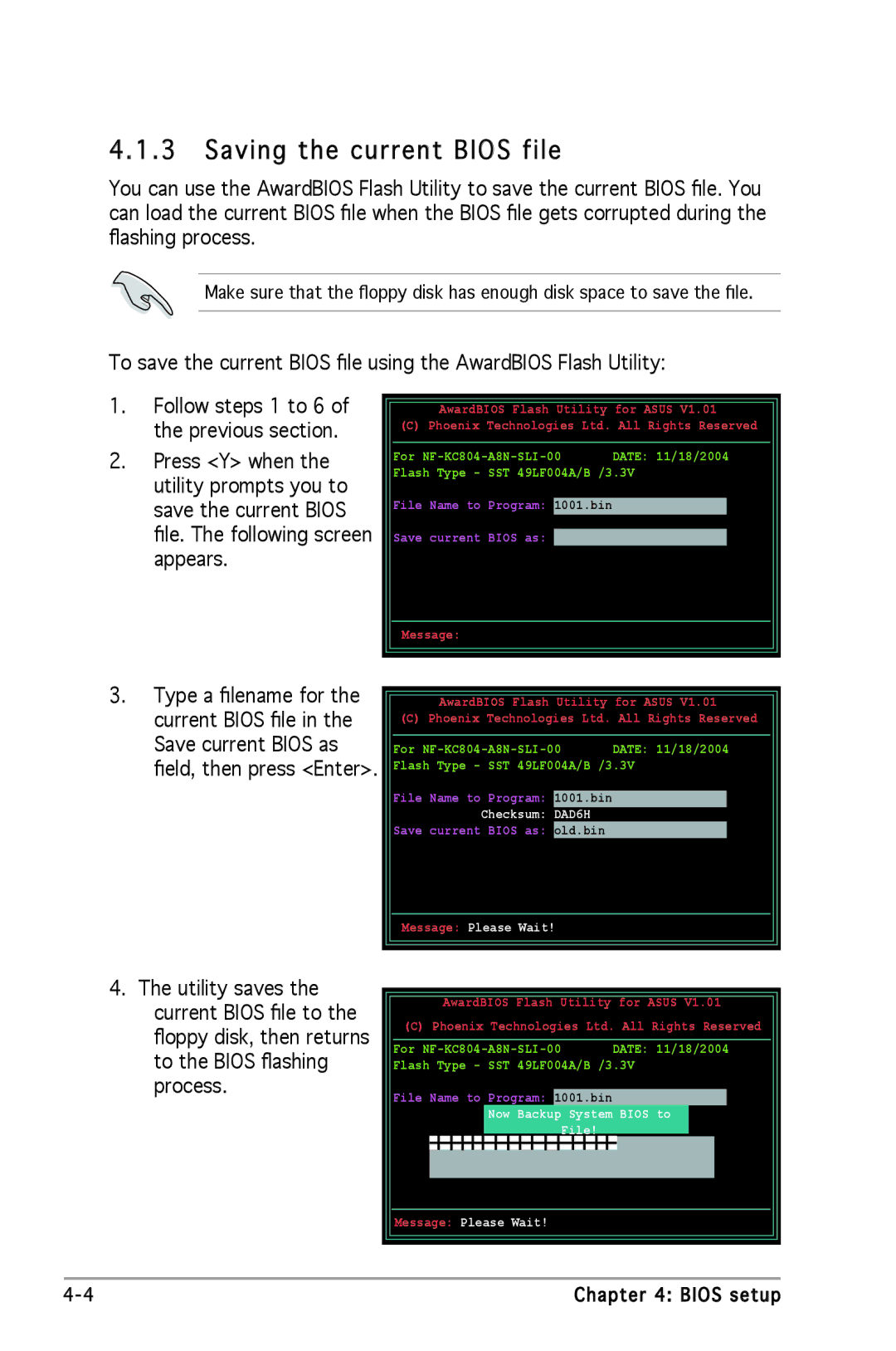
Checksum DAD6H
Saving the current Bios file
System Bios to
Message Please Wait
Asus CrashFree Bios 2 utility
Recovering the Bios from the support CD
Recovering the Bios from a floppy disk
Asus EZ Flash utility
Insert Disk then press Enter or ESC to continue Post
Asus Update utility
Installing Asus Update
Updating the Bios through the Internet
Updating the Bios through a Bios file
Bios setup program
Menu bar
Bios menu screen
Advanced Power Boot Exit
6 Configuration fields
Menu items
Sub-menu items
General help
Advanced Power
Pop-up window
System Date Day xx/xx/xxxx
Main menu
System Time
Legacy Diskette a 1.44M, 3.5
Auto
Access Mode Auto
Primary and Secondary IDE Master/Slave
Transfer Mode
PIO Mode
Udma Mode
Capacity
Extended Drive
Access Mode
First, Second, Third, Fourth Sata Master
Extended IDE Drive Auto
Usable Memory
Installed Memory
HDD Smart Monitoring
Precomp
CPU Configuration
Power Boot Exit
Advanced menu
Main
Dram Configuration
Sets the timing mode. Configuration options Auto Manual
AMD K8 CoolʼnʼQuiet control Disabled
Hyper Transport Frequency Auto
Resources Controlled By Auto
PCI PnP
Plug & Play O/S No
Init Display First PCI
IRQ Resources
IDE Function Setup
Onboard Devices Configuration
IRQ-3 assigned to PCI Device
OnChip IDE Channel1 Enabled
IDE Function Setup
OnChip IDE Channel0 Enabled
IDE DMA transfer access Enabled
RAID Enabled Disabled
SATA2 DMA transfer Enabled
IDE Prefetch Mode Enabled
IDE Primary, Secondary Master/Slave RAID Disabled
USB Legacy Support Enabled
USB Controller Enabled
USB 2.0 Controller Enabled
Onboard NV LAN Enabled
Serial Port1 Address 3F8/IRQ4
Parallel Port Mode ECP+EPP
ECP Mode Use DMA
Parallel Port Address 378/IRQ7
EZ-Plug Warning Enabled
EZ-Plug Warning Enabled
SLI Broadcast Aperture Disabled
SLI Configuration
Overclock Profile Auto
Feature intelligently determines the system
JumperFree Configuration
CPU Frequency XXX value is auto-detected
DDR Voltage Auto
PCI Clock Synchronization Mode Auto
PCI Express Clock 100MHz
CPU Multiplier Auto
S. Option Disable
PEG Link Mode
Overclock Options Disabled
PEG Link Mode Auto
PEG Root Control Auto
PEG Buffer Length Auto
Acpi Suspend Type S1&S3
Power menu
Acpi Apic Support Enabled
Power On By External Modems Disabled
Restore on AC Power Loss Disabled
Power On By PCI Devices Disabled
APM Configuration
Time hhmmss Alarm Disabled
Power On By RTC Alarm Disabled
Day of Month Alarm Disabled
Power Up By PS/2 Mouse Disabled
Hardware Monitor
Fan2 Controller Disabled
CPU Temperature, M/B Temperature
Vcore Voltage, +12V Voltage, 3.3V Voltage, 5VCC Voltage
Chip Fan Speed warning Enabled
CPU Target Temperature
CHA1 Fan Speed warning Disabled
CPU Fan Speed warning 1200 RPM
1st ~ xxth Boot Device Removable
Boot menu
Boot Device Priority
Main Advanced Power
Floppy Disks
Removable Drives
Hard Disk Drives
1st Master
Boot Settings Configuration
Typematic Rate Chars/Sec
Typematic Delay Msec
Full Screen Logo Enabled
OS Select for Dram 64MB Non-OS2
Security
Supervisor Password User Password
Supervisor Password
Press any key to continue
Password Check
Exit & Save Changes
Main Advanced Power Boot
Exit menu
Exit & Discard Changes
Load Setup Defaults
Discard Changes
Software5 support
Chapter summary
Running the support CD
Installing an operating system
Support CD information
Drivers menu
Nvidia Chipset nTune Utility
Asus Update
Utilities menu
Asus PC Probe I
Adobe Acrobat Reader Asus Screen Saver
Installs the Asus Screen Saver
Microsoft DirectX Anti -virus Utility
Nvidia RAID Userʼs Guide
Nvidia Firewall Administratorʼs Guide
Manuals menu
Nvidia nTune Manual
Motherboard Info
Asus Contact information
Other information
Displays the general specifications of the motherboard
Technical support Form
Displays the support CD contents in graphical format
Browse this CD
Filelist
Software information
Asus MyLogo2
Software support
Audio configurations
Sound Effect options
Pdif option
Speaker Configuration
AI Audio feature
Hrtf Demo
General settings
Rear panel audio ports function variation
Using the Nvidia Firewall
Launching the NVFirewall summary
Setting security profiles
Turning the NVFirewall off
RAID configurations
Installing Serial ATA Sata hard disks
Installing hard disks
Installing Parallel ATA hard disks
Nvidia RAID configurations
Setting the Bios RAID items
Creating a RAID Volume
Entering the Nvidia RAID utility
Clear disk data?
Rebuilding a RAID array
↑↓ Select F6 Back F7 Finish
Rebuild array? Enter OK ESC Cancel
Capacity
If you selected Yes, the Define a New Array menu appears
Press Y to delete array or press N to cancel
Deleting a RAID array
Delete this array? YES N No
Press Y to clear the disk data or press N to cancel
Clearing a disk data
Creating a RAID driver disk
Windows 2000/XP
Cool ‘n’ Quiet! Technology
Enabling Cool ʻnʼ Quiet! Technology
Launching the Cool ʻnʼ Quiet! software
Using the Nvidia nTune utility
Managing your nForce system
Clock control
Voltage/Fan control
Information
Other options
Using the Asus AI Selector utility
Launching the Asus AI Selector
Using the SLI mode
To use SLI mode
Nvidia SLI technology support
Overview Dual graphics cards setup
Overview
Requirements
Dual graphics card setup
Installing SLI -ready graphics cards
Asus A8N-SLI SE
SLI flexible cable
Installing the device drivers
Installing the Asus AI Selector utility
Enabling the multi -GPU feature in Windows
Slider
Setting the Asus AI Selector utility
AI Selector settings