1.3Rear panel
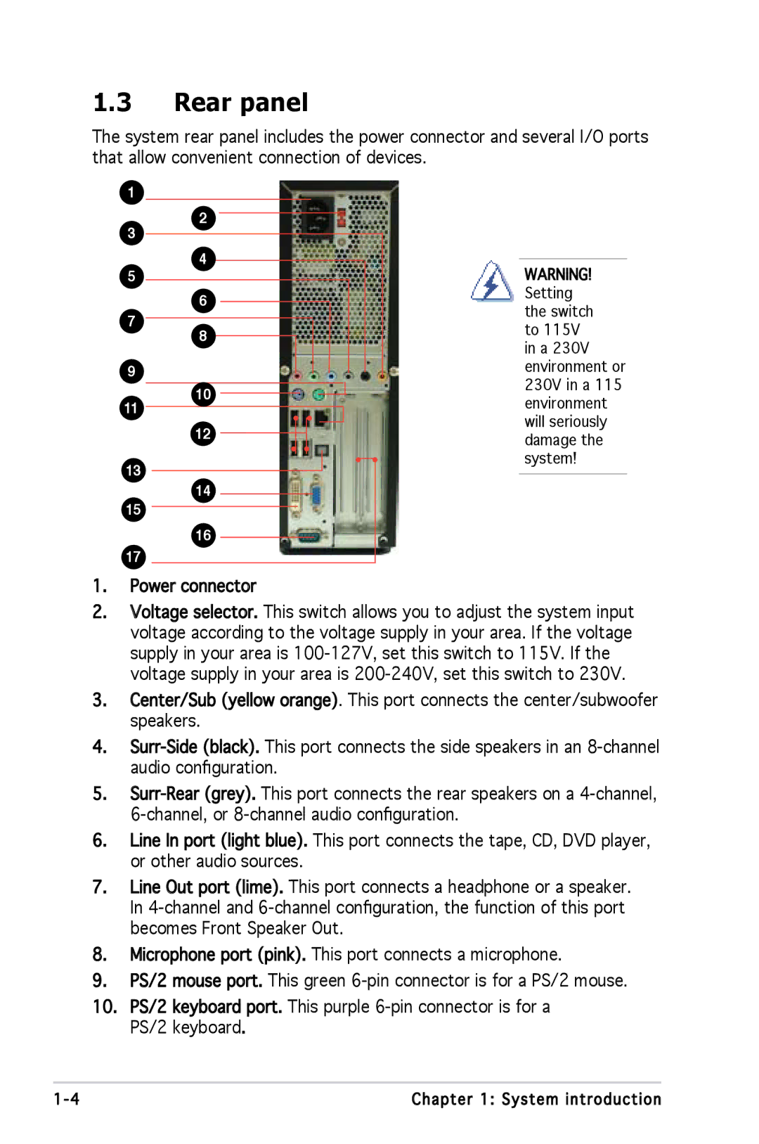
The system rear panel includes the power connector and several I/O ports that allow convenient connection of devices.
1
3
5
7
9
2
4
6
8
WARNING! Setting the switch to 115V in a 230V environment or
1110
12
230V in a 115 environment will seriously damage the system!
13
15
17
14
16
1.Power connector
2.Voltage selector. This switch allows you to adjust the system input voltage according to the voltage supply in your area. If the voltage supply in your area is
3.Center/Sub (yellow orange). This port connects the center/subwoofer speakers.
4.
5.
6.Line![]() In
In![]() port (light blue). This port connects the tape, CD, DVD player, or other audio sources.
port (light blue). This port connects the tape, CD, DVD player, or other audio sources.
7.Line![]() Out port (lime). This port connects a headphone or a speaker.
Out port (lime). This port connects a headphone or a speaker.
In
8.Microphone port (pink). This port connects a microphone.
9.PS/2 mouse port. This green
10.PS/2 keyboard port. This purple
1- | Chapter 1: System introduction |