Motherboard
E1674 First Edition June
Copyright 2004 ASUSTeK Computer INC. All Rights Reserved
Contents
Powering up
Bios setup
Software support
Primary, Third and Fourth IDE Master/Slave
Media 3D audio configuration
Federal Communications Commission Statement
Canadian Department of Communications Statement
Safety information
Electrical safety
Operation safety
Where to find more information
About this guide
How this guide is organized
Typography
Conventions used in this guide
P5GD2 Deluxe specifications summary
Memory
Ieee
Internal
Page
Product introduction
Chapter summary
Asus P5GD2 Deluxe
Package contents
Welcome
Special features
Product highlights
Triple RAID solution
PCI Expressª interface
Channel high definition audio
Dolby¨ Digital Liveª
Temperature, fan, and voltage monitoring
Pdif digital sound ready
USB 2.0 technology
Asus Proactive features
AI NOSª Non-Delay Overclocking System
Asus Stack Cool
AI Net2
Innovative Asus features
Hardware2 information
Chapter summary
Before you proceed
Onboard LED
P5GD2 Deluxe Onboard LED Asus P5GD2 Deluxe
Placement direction
Motherboard overview
Screw holes
Asus Stack Cool
Motherboard layout
24.5cm 9.6in
Layout Contents
Internal connectors G e
Installling the CPU
Central Processing Unit CPU
P5GD2 Deluxe Socket
Load plate
Asus P5GD2 Deluxe
Installling the CPU heatsink and fan
Asus P5GD2 Deluxe
P5GD2 Deluxe CPU fan connector
Memory Configurations
System memory
Overview
P5GD2 Deluxe 184-Pin DDR Dimm sockets
DDR2 533 Qualified Vendors List
M p o n e n t
Installing a Dimm
To install a Dimm
Removing a Dimm
Installing an expansion card
Configuring an expansion card
Expansion slots
Interrupt assignments
Standard interrupt assignments
IRQ assignments for this motherboard
PCI slots
PCI Express x16 slot
PCI Express x1 slot
Jumpers
Clear RTC RAM CLRTC1
P5GD2 Deluxe Clear RTC RAM
USB device wake-up 3-pin USBPW12, USBPW34, USBPW56, USBPW78
P5GD2 Deluxe USB device wake-up
Keyboard power 3-pin KBPWR1
P5GD2 Deluxe Keyboard power setting Asus P5GD2 Deluxe
Connectors
Rear panel connectors
LAN port LED indications
Wireless LAN LED indications
Audio 2, 4, 6, or 8-channel configuration
Internal connectors
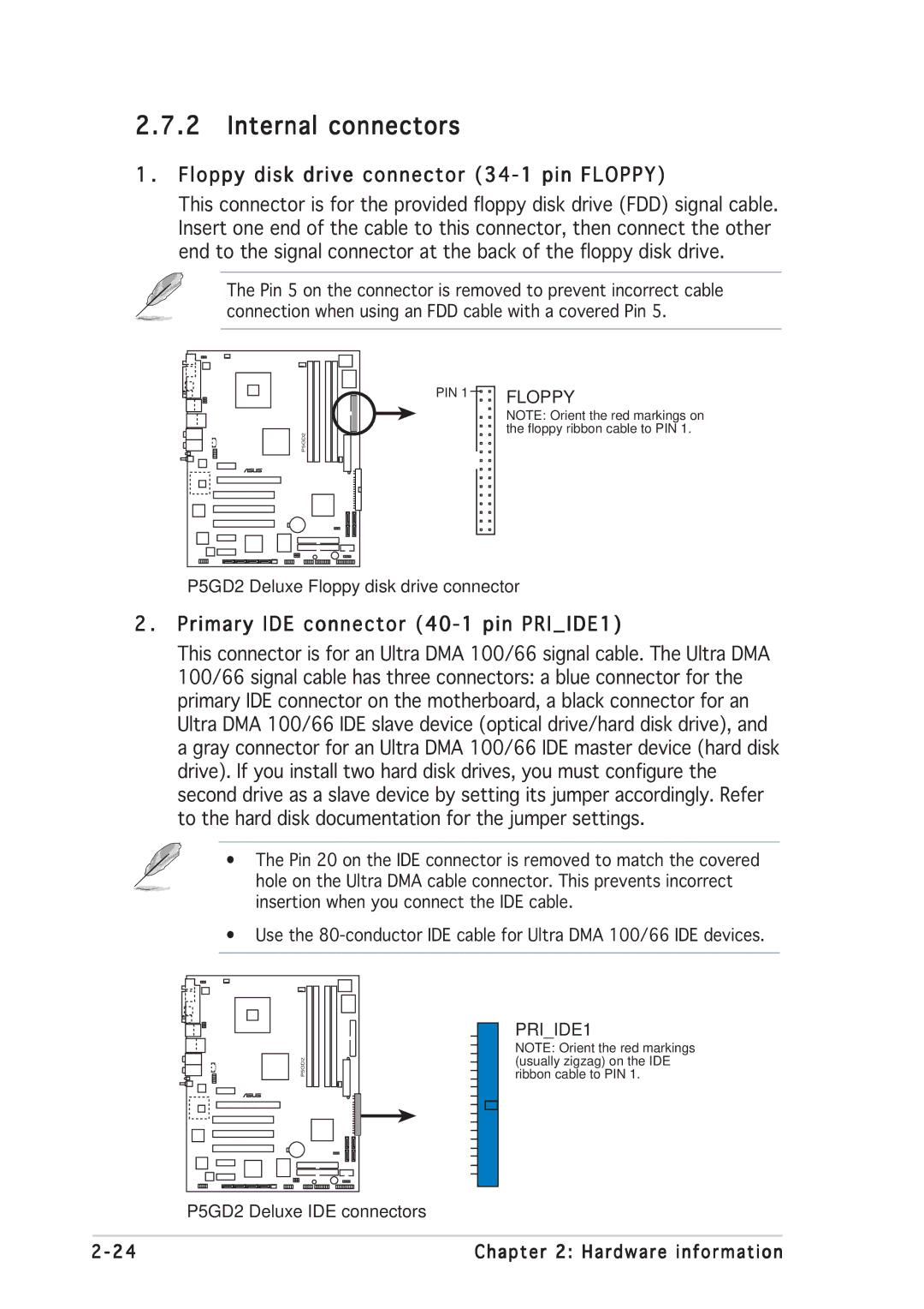
Floppy disk drive connector 34-1 pin Floppy
Primary IDE connector 40-1 pin PRIIDE1
P5GD2 Deluxe Floppy disk drive connector
IDE RAID connectors 40-1 pin PRIRAID1 red, SECRAID1 red
P5GD2 Deluxe RAID connectors
Serial ATA Master/Slave connectors
P5GD2 Deluxe Sata connectors Important notes on Serial ATA
P5GD2 Deluxe Sata RAID connectors
SATARAID1 SATARAID3
P5GD2 Deluxe Fan connectors
Serial port connector 10-1 pin COM1
USB connectors 10-1 pin USB56, USB78
P5GD2 Deluxe COM port connectors
P5GD2 Deluxe USB 2.0 connectors
ATX power connectors 24-pin EATXPWR1, 4-pin ATX12V1
P5GD2 Deluxe ATX power connectors
Optical drive audio connector 4-pin CD
GAME/MIDI port connector 16-1 pin GAME1
P5GD2 Deluxe CD audio connector
P5GD2 Deluxe Game connector
Chassis intrusion connector 4-1 pin CHASSIS1
Front panel audio connector 10-1 pin Aafp
P5GD2 Deluxe Chassis alarm lead
P5GD2 Deluxe Front panel connector
System panel connector 20-pin PANEL1
¥ System power LED Green 3-pin Pled
¥ Reset button Blue 2-pin Reset
P5GD2 Deluxe System panel connector
Hardware information
Powering up
Chapter summary
AMI Bios beep codes
Starting up for the first time
Powering off the computer
Using the OS shut down function
Using the dual function power switch
Asus Post Reporter
Vocal Post messages
Powering up
Playing the default wave files
Winbond Voice Editor
Launching the Voice Editor
Start All Programs Winbond Voice Editor Voice Editor
Changing the default language
Customizing your Post messages
Powering up
Bios setup
Chapter summary
Managing and updating your Bios
Creating a bootable floppy disk
Asus EZ Flash utility
Copying the current Bios
Afudos utility
Updating the Bios file
To update the Bios file using the Afudos utility
Asus CrashFree Bios 2 utility
Recovering the Bios from a floppy disk
Recovering the Bios from the support CD
Asus Update utility
Installing Asus Update
Updating the Bios through the Internet
Updating the Bios through a Bios file
Bios setup program
Bios menu screen
Menu bar
Navigation keys
Configuration fields
Menu items
Sub-menu items
Pop-up window
Main menu
System Time
System Date Day xx/xx/xxxx
Legacy Diskette a 1.44M, 3.5
LBA/Large Mode Auto
Primary, Third and Fourth IDE Master/Slave
Type Auto
Block Multi-sector Transfer Auto
IDE Configuration
Alpe and ASP Disabled
IDE Detect Time Out
System Information
Processor
System Memory
JumperFree Configuration
Advanced menu
AI Overclocking Auto
CPU Clock Spread Spectrum Enabled
Pcie Clock Spread Spectrum Enabled
CPU VCore Over Voltage Control Disabled
Dram Frequency Auto
Sata Clock Sync to Pciex Disabled
PCI Clock Synchronization Mode Asynchronization
FSB Termination Voltage Auto
CPU to NB Trapping Auto
LAN Cable Status
Overclock Options Overclock 5%
USB Configuration
CPU Configuration
Hyper-Threading Technology Enabled
Chipset
Booting Graphic Adapter Priority PCI Express/PCI
PEG Buffer Length Auto
Onboard Devices Configuration
ITE8212F Controller IDE Mode
Silicon Image Controller Enabled
Parallel Port Mode ECP
Serial Port1 Address 3F8/IRQ4
Onboard Game/MIDI Port Disabled
PCI Latency Timer
PCI PnP
Plug And Play O/S No
Speech Configuration
Power menu
Suspend Mode Auto
Acpi Apic Support Enabled
Repost Video on S3 Resume No
APM Configuration
Power Button Mode On/Off
Restore on AC Power Loss Power Off
Power On By RTC Alarm Disabled
Power On By PCI Devices Disabled
Power On By PS/2 Keyboard Disabled
Wakeup Password
Power On By PS/2 Mouse Disabled
CPU Temperature xxxC/xxxF MB Temperature xxxC/xxxF
CPU Q-Fan Control Disabled
Hardware Monitor
CPU Fan Speed xxxxRPM or N/A
CPU Target Temperature xxx¼C
Chassis Q-Fan Control Disabled
Power Fan Speed xxxxRPM or N/A
Chassis Fan Speed xxxxRPM or N/A
Boot menu
Boot Device Priority
1st ~ xxth Boot Device 1st Floppy Drive
Boot Settings Configuration
Hit Ôdelõ Message Display Enabled
Interrupt 19 Capture Disabled
Change Supervisor Password
Security
User Access Level Full Access
Change User Password
Clear User Password
Password Check Setup
Boot Sector Virus Protection Disabled
Exit menu
Load Setup Defaults
Exit & Save Changes
Exit & Discard Changes
Discard Changes
Software5 support
Installing an operating system
Installing an operating system
Support CD information
Running the support CD
Drivers menu
Utilities menu
Asus Update
AI Booster
Microsoft DirectX
PC-cilllin
Manuals menu
Asus Contact information
Other information
Motherboard Info
Browse this CD
Technical support Form
Filelist
Software information
Asus MyLogo2ª
Asus P5GD2 Deluxe
Using the Virtual Cable Testerª
AI NET2
Media 3D audio configuration
Launching the C-Media 3D Audio Configuration utility
Using the C-Media 3D Audio Configuration utility
Mixer
Effect
Device Setting
RAID configurations
Installing hard disks
Installing Parallel ATA hard disks
Installing Serial ATA Sata hard disks
Silicon Image RAID configurations
Setting the Bios RAID items
Launching the Silicon Image Array Management Software
Entering the Silicon Image Bios RAID Configuration Utility
Enter
Ctrl-E
Auto configuration
Creating a RAID 0 set Striped
Manual configuration
Creating a RAID 1 set Mirrored
Manual configuration
Creating a RAID 10 set Mirrored+Striped
Select RAID 10 then press Enter to display the following
Xxxxxxxxxxx
Creating a RAID 5 or Jbod set
Intel¨ RAID configurations
Set the OnBoard Serial-ATA Bootrom item as Enabled
Creating a RAID Volume
Create Array Menu
Deleting a RAID Volume
Delete Array Menu
Resetting RAID Disks Drives
Reset RAID Data
4 ITE¨ 8212F RAID configurations
Entering the ITE¨ 8212F Setup Utility
Auto-configuring a RAID array
Setup Array Type as
Defining a RAID array
Deleting a RAID array
Rebuilding a RAID array
Viewing your RAID configuration
Creating a RAID driver disk
Software support