Installation
Before you begin, make sure that power to all the devices (Master View Pro and PCs) you will be connecting up have been turned off.
First Stage Installation
In a Single Stage installation, there are no additional Master View’s daisy chained down from the first unit. To set up a single stage installation do the following:
1.Set Switches 1 - 5 of the Master View Pro’s DIP Switch to the ON position to set this unit up as the First Station (see the table on page 26 for Dip Switch Station Setting details).
2.To enable Hot Key port selection (see p.13, for details concerning Hot Key Port Selection), set DIP Switch 6 to the ON position.
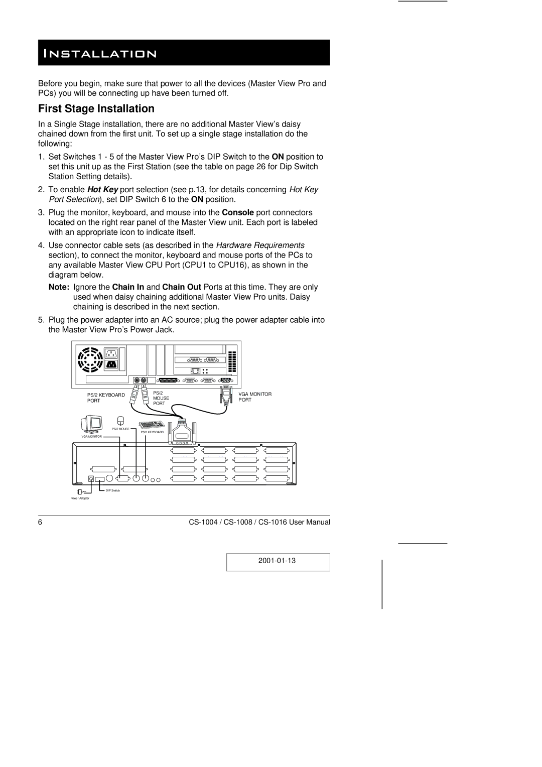
3.Plug the monitor, keyboard, and mouse into the Console port connectors located on the right rear panel of the Master View unit. Each port is labeled with an appropriate icon to indicate itself.
4.Use connector cable sets (as described in the Hardware Requirements section), to connect the monitor, keyboard and mouse ports of the PCs to any available Master View CPU Port (CPU1 to CPU16), as shown in the diagram below.
Note: Ignore the Chain In and Chain Out Ports at this time. They are only used when daisy chaining additional Master View Pro units. Daisy chaining is described in the next section.
5.Plug the power adapter into an AC source; plug the power adapter cable into the Master View Pro’s Power Jack.
PS/2 KEYBOARD | PS/2 | |
MOUSE | ||
PORT | ||
PORT | ||
|
VGA MONITOR PORT
PS/2 MOUSE
VGA MONITOR
PS/2 KEYBOARD
|
|
|
|
|
|
|
|
|
|
|
|
|
| DIP Switch | |||
|
|
|
|
| ||||
| Power Adapter | |||||||
|
|
|
|
|
|
|
| |
6 |
|
|
|
| ||||
|
|
|
|
| ||||
|
|
| ||||||
|
|
|
|
|
|
|
|
|