Manuals
/
ATON
/
Home Audio
/
Stereo Amplifier
ATON
A275
installation manual
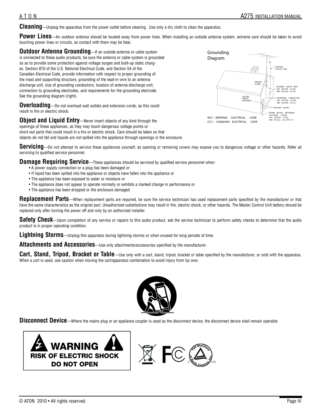
Grounding Diagram
Models:
A275
1
4
54
54
Download
54 pages
8.48 Kb
1
2
3
4
5
6
7
8
Troubleshooting
Specs
Install
Grounding Diagram
Wiring Considerations
Warranty
Pull-OutAccess Door
Setting Channel Levels
Volume
Safety
Page 4
Image 4
Page 3
Page 5
Page 4
Image 4
Page 3
Page 5
Contents
INSTALLATION MANUAL
Two-ChannelPower Amplifier
A275
Purpose of This Manual
Preface
Organization
IMPORTANT SAFETY INFORMATION
RISK OF ELECTRIC SHOCK DO NOT OPEN
Grounding Diagram
A275 INSTALLATION MANUAL
A T O N
Page
ATON 2010 All rights reserved
Table of Contents
Chapter 1 Introduction
Chapter 2 A275 System Design Overview
Chapter 3 A275 Connections
Power Amplifier
A275 Two-ChannelPower Amplifier
Rack Mount Brackets Installation Manual
A275
A275 Features
Individual Channel Level Adjustment
Safety Concerns
AC Power Considerations
A275 Front Panel Functions and Indicators
2BACK
A275 Back Panel
FRONT
Wiring Considerations
SETTING UP THE A275 WITH A DLA SPEAKER SELECTOR
Speaker Wires
Chapter 2. System Design & Applications
DLA4 SPEAKER SELECTOR
Wiring Considerations
Speaker Wires
HOME THEATER RECEIVER
4/6/8 Ohm Speakers with Volume Controls
Applications
System Design Considerations
Speakers
Multi-Room
IMPORTANT NOTE
Stereo Sub-Zones
Speakers
VOLUME
IMPORTANT NOTE
Outdoor
Speakers
Chapter 3 Connections
From Audio
RCA Patch Cable
Output Source
A275 #1
A275 #2
Line Ouputs
From Audio Output Source
WHITERED
GREENBLACK
Speaker Binding Post
Figure 3-3 Speaker Binding Post
Triggers
AH66T
From AH66T
#3-4
Chapter 4 Operations & Settings
FactoryFactoryDefault
Defaultis 85%50%
Setting Channel Levels
Chapter 5 Troubleshooting
Technical Support
Appendix A Specifications
Appendix B: Rack Mounting
Rack-MountBracket
Figure B-1
Figure B-2
Rack Screws
19 Equipment Rack
Figure B-3
A T O N
A275 INSTALLATION MANUAL
Page
A T O N
LIMITED WARRANTY
ATTENTION TO OUR VALUED CONSUMERS
LIMITADA GARANTÍA
com.atonhome.www
REV 9803392 P/N
CONSUMIDORES ESTIMADOS NUESTROS A ATENCIÓN
NOTAS
19 Página
INSTALACIÓN DE MANUAL A275
N O T A
N O T A
NOTAS
reservados derechos los Todos 2010 ATON
pulg 19 de
equipo de Bastidor
bastidor para Tornillos
3-BFigura
2-BFigura
soporte en Montaje B Apéndice
1-BFigura
Especificaciones A Apéndice
Peso
Activadores
Consumo
técnica Asistencia
problemas de Resolución 5 Capítulo
NIVEL
NIVEL
2 .no A275
1 .no A275
A275
AH66T
NEGRO
VERDE
ROJO
BLANCO
2 .no A275
1 .no A275
RCA Cable
fuente la de audio de salida Desde
A275
Conexiones 3 Capítulo
fuente la de audio de
salida Desde
A275
exterior de
exterior de
Altavoces
habitaciones múltiples en
A275
Altavoces
estéreo Subzonas
Aplicaciones
sistema del diseño al cuanto en Consideraciones
línea de nivel
de analógica
CASA EN CINE PARA RECEPTOR
RCA Cable
línea de nivel
de analógica
aplicaciones y sistema de Diseño .2 Capítulo
CASA EN CINE PA RECEPTOR
¡Importante
cableado al cuanto en Consideraciones
FUNCIÓN
FUNCIÓN
ELEMENTO
FRONTAL PARTE
Introducción 1 Capítulo
A275 del Características
potencia de Amplificador A275
caja la de Contenido
instalación de Manual
soporte en montaje para Escuadras
Índice
IV Página
N O T A
INSTALACIÓN DE MANUAL A275
ADVERTENCIA
de Diagrama
ABRIR NO ELÉCTRICA DESCARGA DE RIESGO
reservados derechos los Todos 2010 ATON
PRECAUCIÓN
SEGURIDAD DE IMPORTANTE INFORMACIÓN
ADVERTENCIA
manual este de Propósito
Prólogo
Organización
A275
INSTALACIÓN DE MANUAL
canales dos de potencia de Amplificador
Top
Page
Image
Contents