6![]() :
:
(a)Display Channel 1 in
(b)When in the OSD menu, pressing button is equivalent to entering the number "1".
7![]() :
:
(a)Display Channel 2 in
(b)Pressing this button is equivalent to entering the number "2" when in the OSD menu.
8![]() :
:
(a)Display Channel 3 in
(b)Pressing this button is equivalent to entering the number "3" when in the OSD menu.
9![]() :
:
(a)Display Channel 4 in
(b)Pressing this button is equivalent to entering the number "4" when in the OSD menu.
10![]() :
:
Display cameras in quad screen.
11X :
| (a) Display the Playlist. | (b) Play back a recording. |
12 | / : |
|
| (a) Pause playback. | (b) Pause/Stop recording. |
13: Fast reverse during playback.
14:
(a)Fast forward during playback.
(b)Toggle between the Playlist and the date/time search controls.
15Removable hard disk rack with lock
![]() CAUTION
CAUTION
BEFORE REMOVING THE REMOVABLE OR INTERNAL HARD DISK, POWER OFF THE DVR UNIT FIRST.
16Removable Power LED
17Removable Hard disk LED
18Hard disk LED
19DVR Power LED
20USB2.0 Socket
5
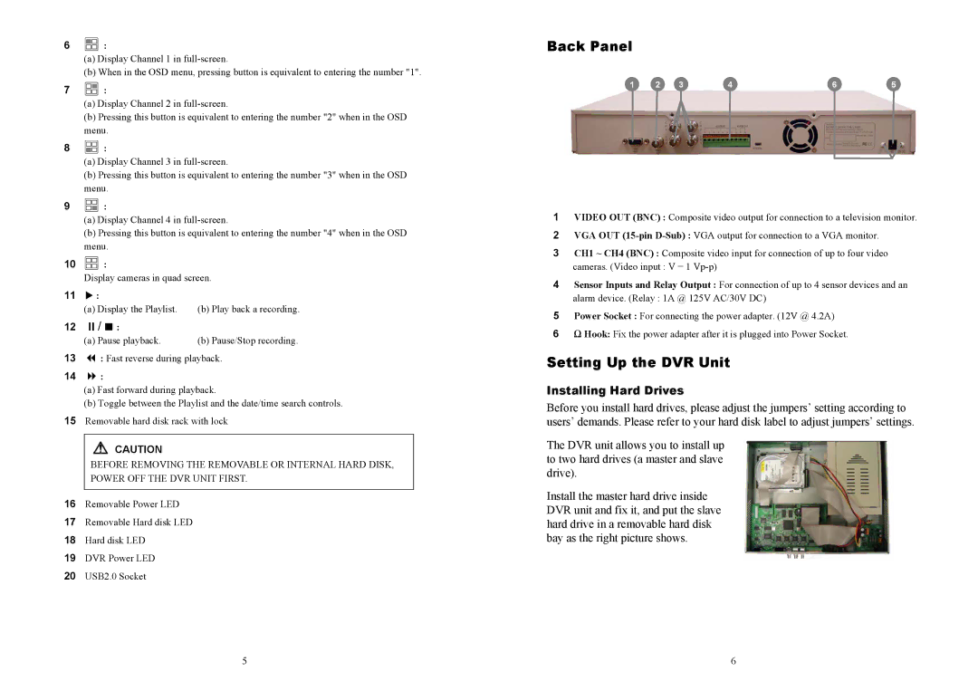
Back Panel
1 | 2 | 3 | 4 | 6 | 5 |
1VIDEO OUT (BNC) : Composite video output for connection to a television monitor.
2VGA OUT
3CH1 ~ CH4 (BNC) : Composite video input for connection of up to four video
cameras. (Video input : V = 1
4Sensor Inputs and Relay Output : For connection of up to 4 sensor devices and an
alarm device. (Relay : 1A @ 125V AC/30V DC)
5Power Socket : For connecting the power adapter. (12V @ 4.2A)
6Ω Hook: Fix the power adapter after it is plugged into Power Socket.
Setting Up the DVR Unit
Installing Hard Drives
Before you install hard drives, please adjust the jumpers’ setting according to users’ demands. Please refer to your hard disk label to adjust jumpers’ settings.
The DVR unit allows you to install up to two hard drives (a master and slave drive).
Install the master hard drive inside DVR unit and fix it, and put the slave hard drive in a removable hard disk bay as the right picture shows.
6