AXIS 221 - The I/O Units Connectors 43
The I/O Units Connectors
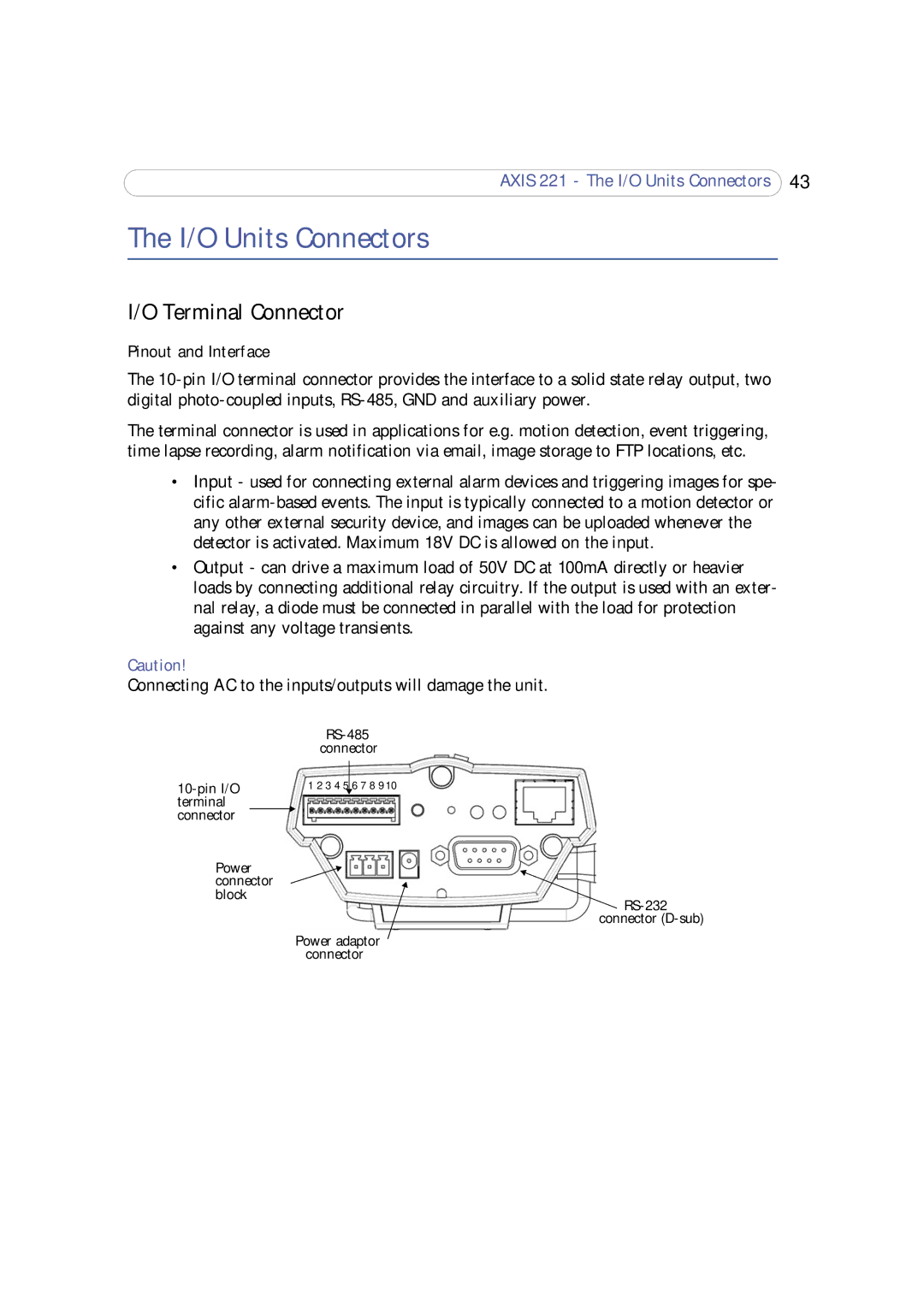
I/O Terminal Connector
Pinout and Interface
The
The terminal connector is used in applications for e.g. motion detection, event triggering, time lapse recording, alarm notification via email, image storage to FTP locations, etc.
•Input - used for connecting external alarm devices and triggering images for spe- cific
•Output - can drive a maximum load of 50V DC at 100mA directly or heavier loads by connecting additional relay circuitry. If the output is used with an exter- nal relay, a diode must be connected in parallel with the load for protection against any voltage transients.
Caution!
Connecting AC to the inputs/outputs will damage the unit.
|
| |||
|
| connector | ||
|
| |||
1 2 3 4 5 |
| 6 7 8 9 10 | ||
| ||||
terminal |
|
|
| |
connector |
|
|
|
|
Power |
|
|
| |
connector |
|
|
| |
block |
|
| ||
|
|
|
| |
|
|
|
| connector |
|
| Power adaptor | ||
|
| connector | ||