46AXIS 221 - Unit Connectors
Unit Connectors
This section describes the following:
•The I/O Terminal connector
•Power connections
•The
I/O Terminal connector
The
The terminal connector is used in applications for e.g. motion detection, event triggering, time lapse recording, alarm notification via
•Input - Used for connecting external alarm devices and triggering images for specific
•Output - This can drive a maximum load of 50VDC or 35VAC at 100mA directly or heavier loads by connecting additional relay circuitry. If the output is used with an external relay, a diode must be connected in parallel with the load for protection against any voltage transients.
Caution!
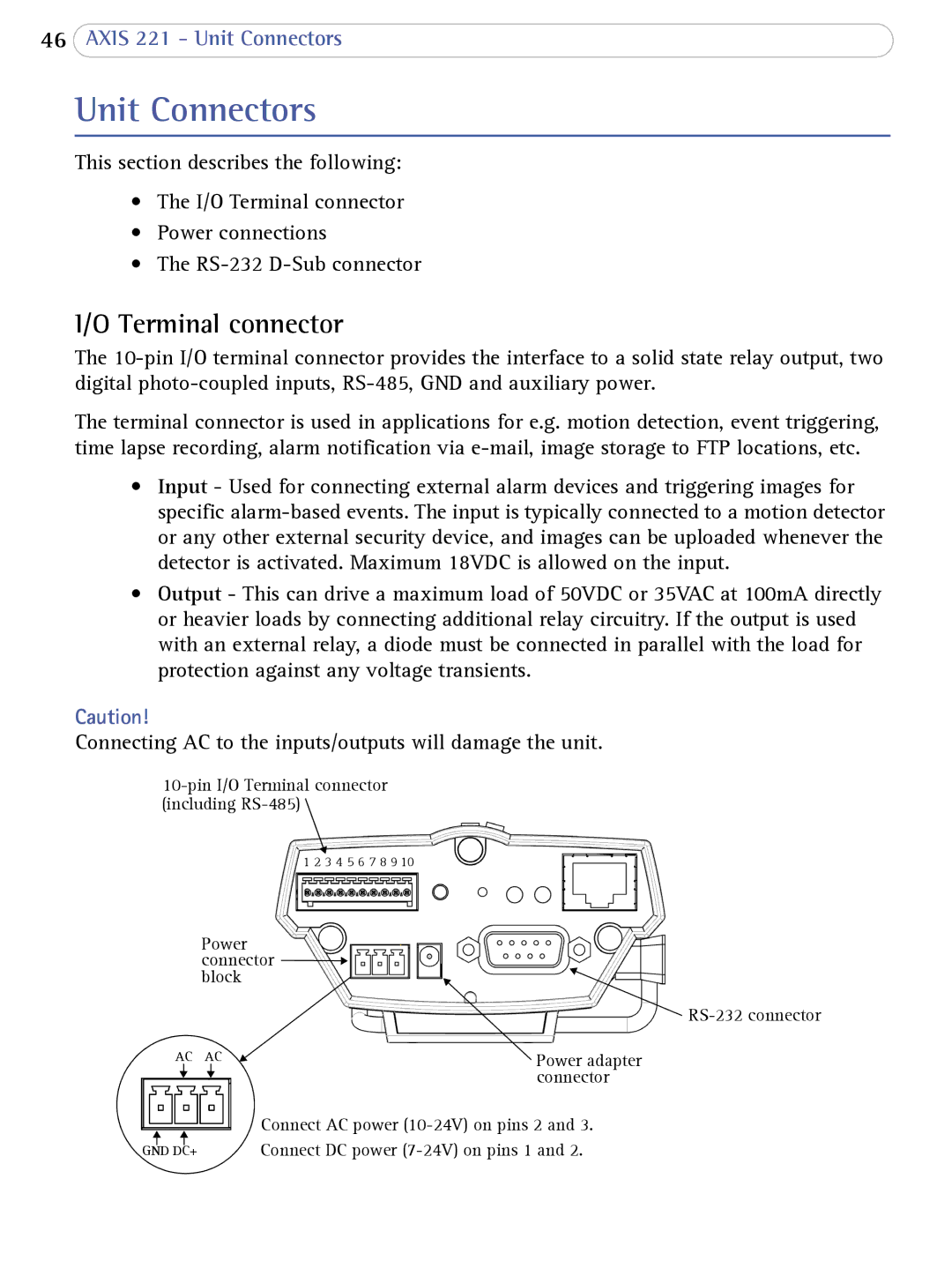
Connecting AC to the inputs/outputs will damage the unit.
![]()
| 1 2 3 4 5 6 7 8 9 10 |
Power |
|
connector |
|
block |
|
| |
AC AC | Power adapter |
| connector |
Connect AC power
GND DC+ | Connect DC power |