AXIS Q7406 Installation GuidePage 15
Pin assignments for the I/O Connector of the AXIS Q7900 Rack
Pin | Function | Description |
|
|
|
|
|
|
|
| |
1 | Channel 1, Configurable I/O 1 | Digital input - Connect to GND | Min input = - 40V DC |
|
|
|
| to activate, or leave floating (or | Max input = + 40V DC |
| |
2 | Channel 2, Configurable I/O 1 |
|
| ||
unconnected) to deactivate. |
|
|
| ||
|
|
|
|
| |
3 | Channel 3, Configurable I/O 1 |
|
|
| |
|
|
|
| ||
|
| Digital output - Uses an open- | Max load = 100mA |
| |
4 | Channel 4, Configurable I/O 1 |
|
| ||
|
| drain NFET transistor with the | Max voltage = + 40V DC |
| |
5 | Channel 5, Configurable I/O 1 |
|
| ||
source connected to GND. If | (to the transistor) |
|
| ||
|
|
| |||
6 | Channel 6, Configurable I/O 1 | used with an external relay, a |
|
|
|
|
| ENGLISH | |||
|
| diode must be connected in |
|
| |
7 | Channel 1, Configurable I/O 2 |
|
|
| |
parallel with the load, for |
|
|
| ||
|
|
|
|
| |
8 | Channel 2, Configurable I/O 2 |
|
|
| |
protection against voltage |
|
|
| ||
|
| transients. |
|
|
|
9 | Channel 3, Configurable I/O 2 |
|
|
| |
|
|
| |||
|
|
|
|
|
|
10 | Channel 4, Configurable I/O 2 |
|
|
|
|
|
|
|
|
|
|
11 | Channel 5, Configurable I/O 2 |
|
|
|
|
|
|
|
|
|
|
12 | Channel 6, Configurable I/O 2 |
|
|
|
|
|
|
|
|
|
|
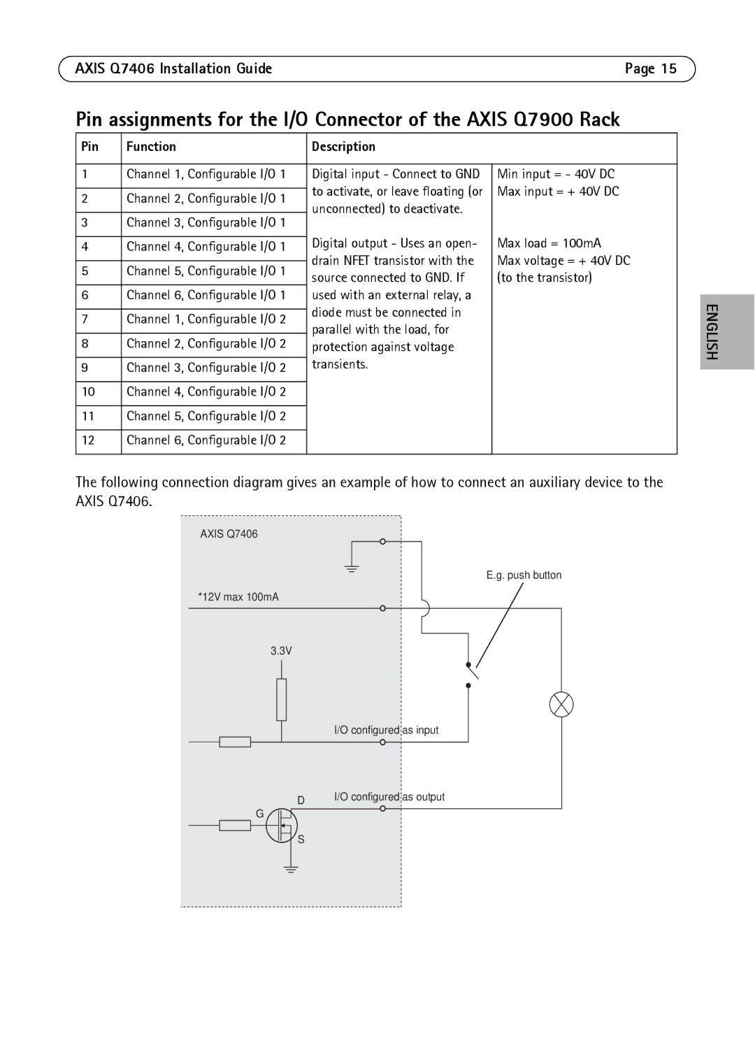
The following connection diagram gives an example of how to connect an auxiliary device to the AXIS Q7406.
AXIS Q7406
*12V max 100mA
E.g. push button
3.3V
I/O configured as input
D | I/O configured as output |
|
G
S