Page 16 | AXIS Q7406 Installation Guide |
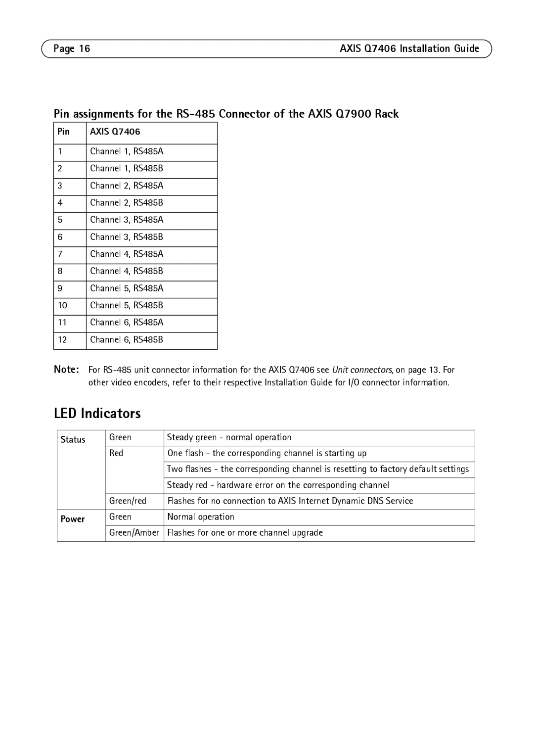
Pin assignments for the
Pin | AXIS Q7406 |
|
|
1 | Channel 1, RS485A |
|
|
2 | Channel 1, RS485B |
|
|
3 | Channel 2, RS485A |
|
|
4 | Channel 2, RS485B |
|
|
5 | Channel 3, RS485A |
|
|
6 | Channel 3, RS485B |
|
|
7 | Channel 4, RS485A |
|
|
8 | Channel 4, RS485B |
|
|
9 | Channel 5, RS485A |
|
|
10 | Channel 5, RS485B |
|
|
11 | Channel 6, RS485A |
|
|
12 | Channel 6, RS485B |
|
|
Note: For
LED Indicators
Status | Green | Steady green - normal operation |
| Red | One flash - the corresponding channel is starting up |
|
|
|
|
| Two flashes - the corresponding channel is resetting to factory default settings |
|
|
|
|
| Steady red - hardware error on the corresponding channel |
|
|
|
| Green/red | Flashes for no connection to AXIS Internet Dynamic DNS Service |
|
|
|
Power | Green | Normal operation |
| Green/Amber | Flashes for one or more channel upgrade |
|
|
|
