AXIS M3027–PVE Fixed Dome Network Camera
Technical Specifications
Function/group | Item | Specifications |
|
|
|
| Dimensions | 132 x 73 mm (5.1 x 2.8 in) |
| (Diameter x |
|
| Height) |
|
|
|
|
| Weight | 740 g (1.6 lb.) |
|
|
|
| Included | Installation Guide, Installation and Management Software CD, drill hole template, |
| accessories | Windows decoder |
| Optional | For indoor use: |
| accessories | AXIS T94F01D Pendant Kit with Network Cable Coupler Indoor |
|
| AXIS T94F01L Recessed Mount Kit with Network Cable Coupler Indoor |
|
| For outdoor use: |
|
| Network Cable Coupler IP66 (can fit inside AXIS T94F02D Pendant Kit) |
|
| AXIS T94F02D Pendant Kit with sunshield |
|
| For indoor or outdoor use: |
|
| AXIS T94F01M |
|
| placed in waterproof area) |
|
| Skin covers |
|
| AXIS T91 Mounting Accessories |
|
| AXIS T94F01P Conduit Back Box |
|
|
|
| Video | AXIS Camera Companion (included), AXIS Camera Station and video management |
| management | software from Axis’ Application Development Partners (not included). See |
| software | www.axis.com/products/video/software |
|
|
|
| Languages | German, French, Spanish, Italian, Russian, Simplified Chinese, Japanese, Korean, |
|
| Portuguese |
|
|
|
Connectors
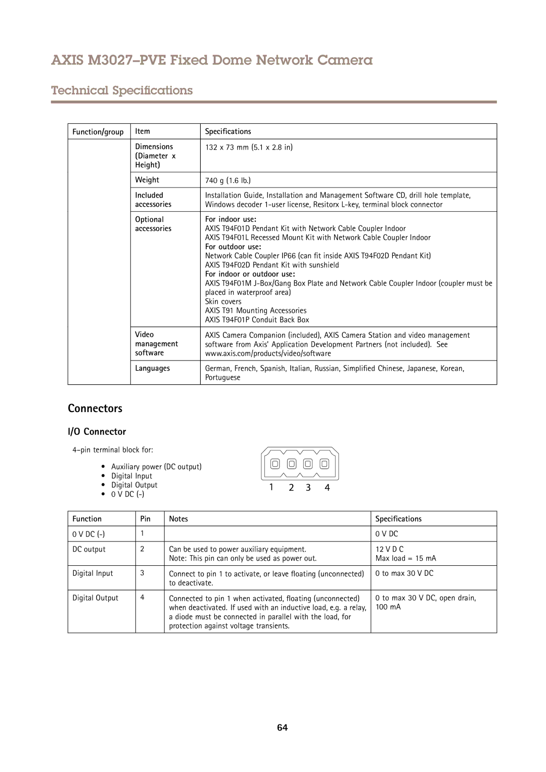
I/O Connector
• Auxiliary power (DC output)
• Digital Input
• Digital Output
• 0 V DC
Function | Pin | Notes | Specifications |
|
|
|
|
0 V DC | 1 |
| 0 V DC |
|
|
|
|
DC output | 2 | Can be used to power auxiliary equipment. | 12 V D C |
|
| Note: This pin can only be used as power out. | Max load = 15 mA |
|
|
|
|
Digital Input | 3 | Connect to pin 1 to activate, or leave floating (unconnected) | 0 to max 30 V DC |
|
| to deactivate. |
|
|
|
|
|
Digital Output | 4 | Connected to pin 1 when activated, floating (unconnected) | 0 to max 30 V DC, open drain, |
|
| when deactivated. If used with an inductive load, e.g. a relay, | 100 mA |
|
| a diode must be connected in parallel with the load, for |
|
|
| protection against voltage transients. |
|
|
|
|
|
64