![]()
![]()
![]()
![]() X7DBi+ User's Manual
X7DBi+ User's Manual
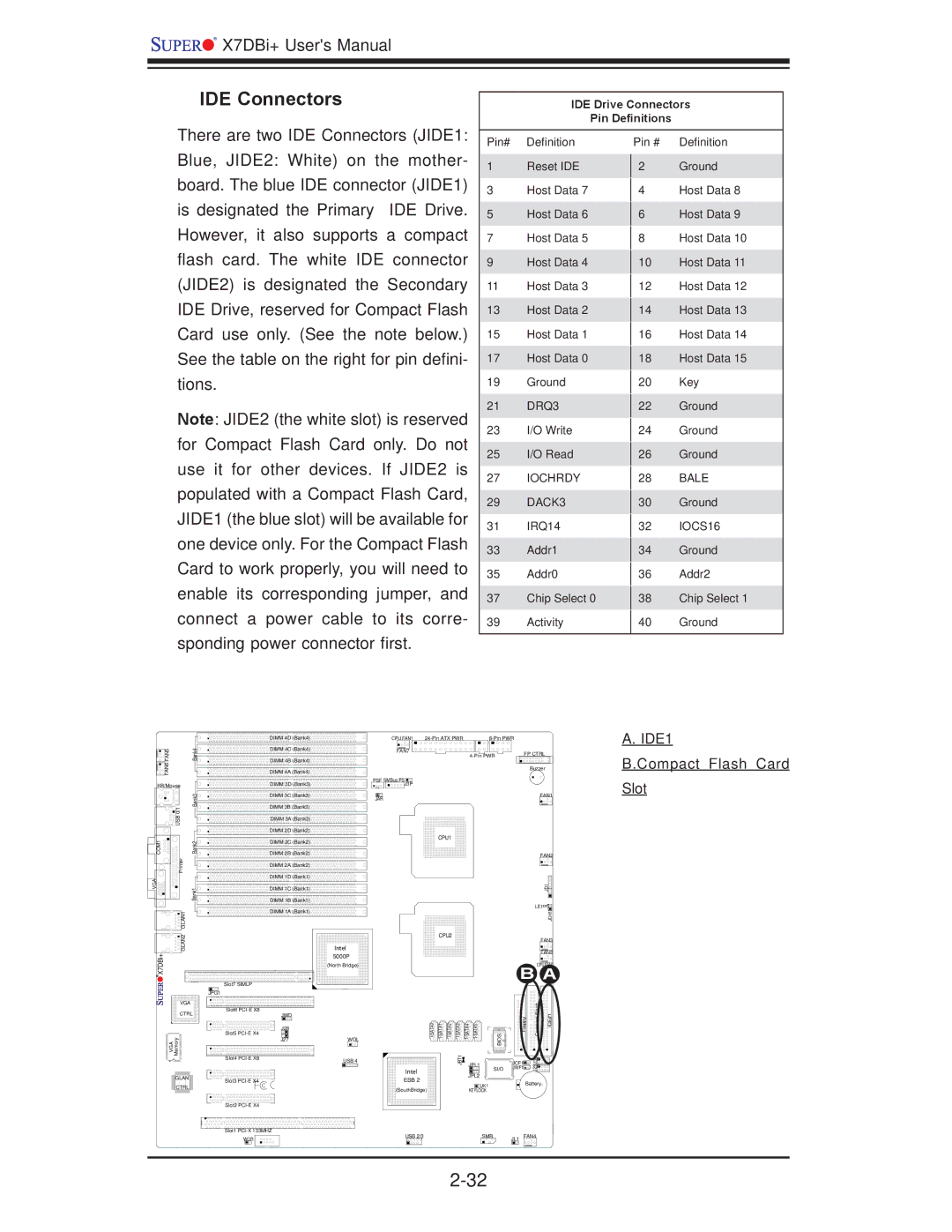
IDE Connectors
IDE Drive Connectors
Pin Definitions
There are two IDE Connectors (JIDE1: Blue, JIDE2: White) on the mother- board. The blue IDE connector (JIDE1) is designated the Primary IDE Drive. However, it also supports a compact flash card. The white IDE connector (JIDE2) is designated the Secondary IDE Drive, reserved for Compact Flash Card use only. (See the note below.) See the table on the right for pin defini- tions.
Note: JIDE2 (the white slot) is reserved for Compact Flash Card only. Do not use it for other devices. If JIDE2 is populated with a Compact Flash Card, JIDE1 (the blue slot) will be available for one device only. For the Compact Flash Card to work properly, you will need to enable its corresponding jumper, and connect a power cable to its corre- sponding power connector first.
Pin# Definition
1Reset IDE
3Host Data 7
5Host Data 6
7Host Data 5
9Host Data 4
11Host Data 3
13Host Data 2
15Host Data 1
17Host Data 0
19Ground
21DRQ3
23I/O Write
25I/O Read
27IOCHRDY
29DACK3
31IRQ14
33Addr1
35Addr0
37Chip Select 0
39Activity
Pin # Definition
2 Ground
4Host Data 8
6Host Data 9
8Host Data 10
10Host Data 11
12Host Data 12
14Host Data 13
16Host Data 14
18Host Data 15
20Key
22Ground
24Ground
26Ground
28BALE
30Ground
32IOCS16
34Ground
36Addr2
38Chip Select 1
40Ground
|
| DIMM 4D (Bank4) | |
FAN5 | Bank4 | DIMM 4C (Bank4) | |
DIMM 4B (Bank4) | |||
FAN6 |
| ||
| DIMM 4A (Bank4) | ||
KB/Mouse |
| DIMM 3D (Bank3) |
CPU FAN1 |
| |
FAN7 | FP CTRL | |
| ||
|
| Buzzer |
PSF SMBus PSJ3P
A. IDE1
B.Compact Flash Card
Slot
Bank3 |
USB 0/1 |
DIMM 3C![]() (Bank3)
(Bank3)
DIMM 3B![]() (Bank3)
(Bank3)
DIMM 3A (Bank3)
DIMM 2D![]() (Bank2)
(Bank2)
JAR
FAN1
COM1 | Bank2 |
| Printer |
VGA | Bank1 |
| GLAN1 |
DIMM 2C (Bank2)
DIMM 2B![]() (Bank2)
(Bank2)
DIMM 2A![]() (Bank2)
(Bank2)
DIMM 1D![]() (Bank1)
(Bank1)
DIMM 1C![]() (Bank1)
(Bank1)
DIMM 1B![]() (Bank1)
(Bank1)
DIMM 1A![]() (Bank1)
(Bank1)
CPU1
FAN2
JD1![]()
LE1![]()
![]()
JOH1
GLAN2 |
Intel |
CPU2
FAN3 |
FAN8 |
X7DBi+
| Slot7 SIMLP | |
| JPG1 | |
VGA |
| |
CTRL | Slot6 | |
JWD | ||
| J28 | |
VGA Memory | Slot5 | |
J27 | ||
Slot4 | ||
| ||
GLAN | Slot3 |
5000P |
(North Bridge) |
WOL
USB 4
Intel |
ESB 2 |
JBT1 | JPL1 |
|
JPL2
| B | CPU FAN2 | ||
|
| A | ||
BIOS | Floppy | Compact Flash | IDE#1 | |
| JCF1 | J29J30 |
| |
SI/O | JWF1 |
| ||
CTRL |
Slot2 |
Slot1 |
(SouthBridge) |
JK1 | Battery |
KEYLOCK |
|
WOR |
USB 2/3 | SMB | JL1 FAN4 |