Chapter 2: Installation
CMOS Clear
JBT1 is used to clear CMOS. Instead of pins, this "jumper" consists of contact pads to prevent the accidental clearing of CMOS. To clear CMOS, use a metal object such as a small screwdriver to touch both pads at the same time to short the connection. Always remove the AC power cord from the system before clearing CMOS. Note: For an ATX power supply, you must completely shut down the system, remove the AC power cord and then short JBT1 to clear CMOS.
Watch Dog Enable/Disable
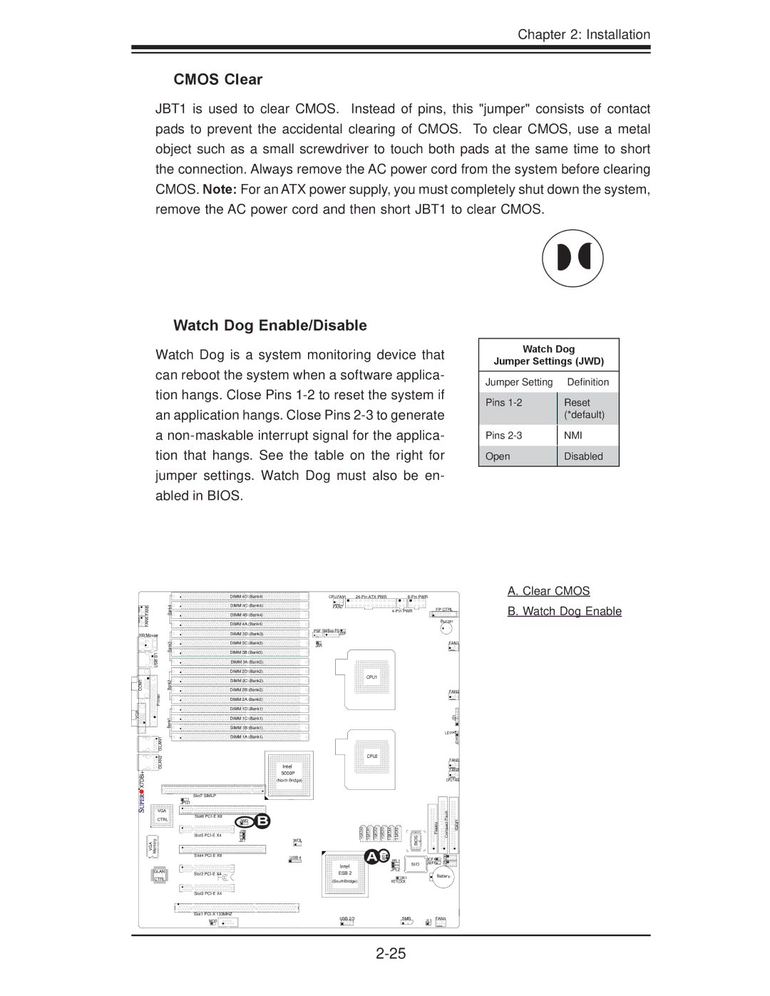
Watch Dog is a system monitoring device that can reboot the system when a software applica- tion hangs. Close Pins
a
Watch Dog
Jumper Settings (JWD)
Jumper Setting |
| Definition |
Pins |
| Reset |
| ||
|
| (*default) |
Pins |
| NMI |
| ||
Open |
| Disabled |
| ||
|
|
|
|
| DIMM 4D (Bank4) | CPU FAN1 |
| ||
FAN5 | Bank4 | DIMM 4C (Bank4) | FAN7 |
|
| FP CTRL |
|
|
|
| |||
|
|
|
|
| ||
FAN6 |
| DIMM 4B (Bank4) |
|
|
|
|
| DIMM 4A (Bank4) |
|
|
| Buzzer | |
|
|
|
|
|
A. Clear CMOS
B. Watch Dog Enable
KB/Mouse
| Bank3 |
| USB 0/1 |
COM1 | Bank2 |
| Printer |
VGA | Bank1 |
DIMM 3D (Bank3)
DIMM 3C![]() (Bank3)
(Bank3)
DIMM 3B![]() (Bank3)
(Bank3)
DIMM 3A (Bank3)
DIMM 2D![]() (Bank2)
(Bank2)
DIMM 2C (Bank2)
DIMM 2B![]() (Bank2)
(Bank2)
DIMM 2A![]() (Bank2)
(Bank2)
DIMM 1D![]() (Bank1)
(Bank1)
DIMM 1C![]() (Bank1)
(Bank1)
DIMM 1B![]() (Bank1)
(Bank1)
PSF SMBus PSJ3P
JAR
CPU1
FAN1
FAN2
JD1![]()
LE1 |
![]()
![]()
![]()
![]()
![]() GLAN2 GLAN1
GLAN2 GLAN1![]()
X7DBi+
VGA
CTRL
Memory
VGA
![]() GLAN
GLAN ![]()
![]() CTRL
CTRL ![]()
Slot7 SIMLP
JPG1
Slot6
Slot5
Slot4
Slot3
DIMM 1A![]() (Bank1)
(Bank1)
CPU2
Intel 5000P
(North Bridge)
JWD | B | BIOS | ||
J28 |
| |||
|
|
|
| |
J27 | WOL |
|
|
|
| USB 4 | A JBT1 | JPL1 |
|
|
| Intel |
| SI/O |
|
| JPL2 |
| |
|
| ESB 2 |
| |
|
| JK1 |
| |
|
| (SouthBridge) |
| |
|
| KEYLOCK |
|
|
| JOH1 |
|
| FAN3 |
|
| FAN8 |
| CPU FAN2 | |
Floppy | Compact Flash | IDE#1 |
JCF1 | J29J30 |
|
JWF1 |
| |
Battery | ||
Slot2 |
|
|
|
|
Slot1 | USB 2/3 | SMB |
| FAN4 |
WOR | JL1 |