![]()
![]()
![]()
![]() X7DBi+ User's Manual
X7DBi+ User's Manual
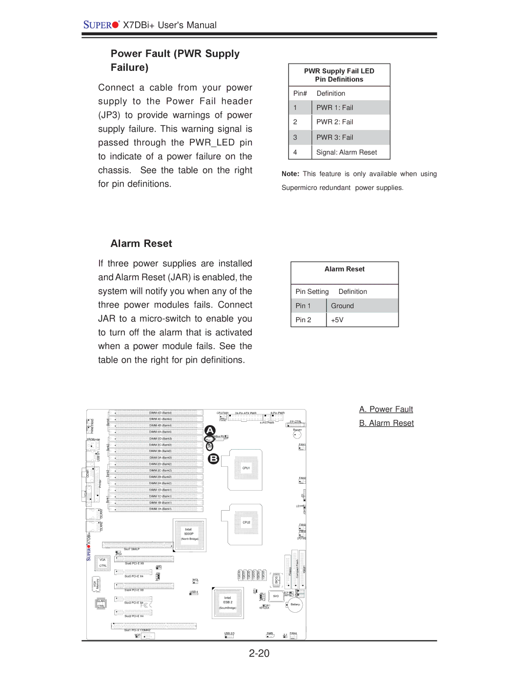
Power Fault (PWR Supply Failure)
Connect a cable from your power supply to the Power Fail header (JP3) to provide warnings of power supply failure. This warning signal is passed through the PWR_LED pin to indicate of a power failure on the chassis. See the table on the right for pin definitions.
Alarm Reset
If three power supplies are installed and Alarm Reset (JAR) is enabled, the system will notify you when any of the three power modules fails. Connect JAR to a
PWR Supply Fail LED
Pin Definitions
Pin# Definition
1PWR 1: Fail
2PWR 2: Fail
3PWR 3: Fail
4Signal: Alarm Reset
Note: This feature is only available when using Supermicro redundant power supplies.
Alarm Reset
Pin Setting | Definition | |
|
| |
Pin 1 |
| Ground |
|
|
|
Pin 2 |
| +5V |
|
|
|
FAN5 | Bank4 |
FAN6 |
|
KB/Mouse |
|
USB 0/1 | Bank3 |
| |
COM1 | Bank2 |
Printer |
|
VGA | Bank1 |
GLAN1 |
|
GLAN2 |
|
X7DBi+ |
|
DIMM 4D (Bank4) | CPU FAN1 |
| ||
DIMM 4C (Bank4) | FAN7 |
|
| FP CTRL |
|
|
| ||
DIMM 4B (Bank4) | A |
|
|
|
DIMM 4A (Bank4) |
|
| Buzzer | |
|
|
|
| |
DIMM 3D (Bank3) | PSF SMBus PSJ3P |
|
|
|
DIMM 3C (Bank3) | JAR |
|
| FAN1 |
|
|
|
| |
DIMM 3B (Bank3) | B |
|
|
|
DIMM 3A (Bank3) |
|
|
| |
DIMM 2D (Bank2) |
|
|
|
|
DIMM 2C (Bank2) |
| CPU1 |
|
|
|
|
|
| |
DIMM 2B (Bank2) |
|
|
| FAN2 |
|
|
|
| |
DIMM 2A (Bank2) |
|
|
|
|
DIMM 1D (Bank1) |
|
|
|
|
DIMM 1C (Bank1) |
|
|
| JD1 |
DIMM 1B (Bank1) |
|
|
| LE1 |
DIMM 1A (Bank1) |
|
|
| |
|
|
| JOH1 | |
|
|
|
|
| CPU2 | |
| FAN3 | |
Intel | FAN8 | |
5000P | ||
| ||
(North Bridge) | CPU FAN2 | |
Slot7 SIMLP |
|
JPG1
A. Power Fault B. Alarm Reset
VGA
CTRL
Memory
VGA
![]() GLAN
GLAN ![]()
![]() CTRL
CTRL ![]()
Slot6
JWD
J28
Slot5
J27
Slot4
Slot3
Slot2
Slot1
WOR
WOL
USB 4
BIOS | Floppy | Compact Flash | IDE#1 |
JBT1 | SI/O | JWF1 | J29J30 |
| JPL1 | JCF1 |
|
|
|
| |
Intel | JPL2 |
|
|
ESB 2 |
|
| |
JK1 |
| Battery | |
(SouthBridge) |
| ||
KEYLOCK |
|
| |
USB 2/3 | SMB | JL1 FAN4 | |