![]()
![]()
![]()
![]() X7DBi+ User's Manual
X7DBi+ User's Manual
2-7 Onboard Indicators
GLAN LEDs
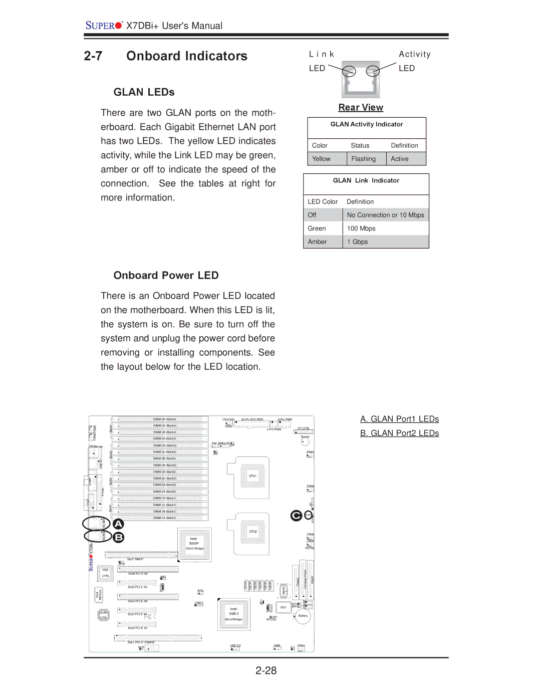
There are two GLAN ports on the moth- erboard. Each Gigabit Ethernet LAN port has two LEDs. The yellow LED indicates activity, while the Link LED may be green, amber or off to indicate the speed of the connection. See the tables at right for more information.
L i n k | Activity |
LED | LED |
Rear View
GLAN Activity Indicator
| Color |
| Status | Definition | |
|
|
|
|
|
|
| Yellow |
| Flashing | Active | |
|
|
|
|
| |
|
|
|
|
|
|
| GLAN Link Indicator | ||||
|
|
|
|
|
|
| LED Color | Definition |
|
| |
| Off |
| No Connection or 10 Mbps | ||
|
| ||||
| Green |
| 100 Mbps |
|
|
|
|
|
| ||
| Amber |
| 1 Gbps |
|
|
|
|
|
| ||
|
|
|
|
|
|
Onboard Power LED
There is an Onboard Power LED located on the motherboard. When this LED is lit, the system is on. Be sure to turn off the system and unplug the power cord before removing or installing components. See the layout below for the LED location.
|
| DIMM 4D (Bank4) | |
FAN5 | Bank4 | DIMM 4C (Bank4) | |
DIMM 4B (Bank4) | |||
FAN6 |
| ||
| DIMM 4A (Bank4) | ||
KB/Mouse |
| DIMM 3D (Bank3) |
CPU FAN1 |
| |
FAN7 | FP CTRL | |
| ||
|
| Buzzer |
PSF SMBus PSJ3P
A. GLAN Port1 LEDs B. GLAN Port2 LEDs
| Bank3 | DIMM 3C (Bank3) | |
0/1 | DIMM 3B (Bank3) | ||
| |||
|
| ||
USB |
| DIMM 3A (Bank3) | |
|
| ||
|
| DIMM 2D (Bank2) |
JAR
FAN1
COM1 | Bank2 | DIMM 2C (Bank2) | |
DIMM 2B (Bank2) | |||
Printer |
| DIMM 2A (Bank2) | |
|
| ||
VGA |
| DIMM 1D (Bank1) | |
Bank1 | DIMM 1C (Bank1) | ||
DIMM 1B (Bank1) | |||
|
| ||
GLAN1 |
| DIMM 1A (Bank1) | |
| A |
CPU1
FAN2
JD1![]()
![]()
![]()
C LE1![]()
![]()
![]()
![]()
![]()
JOH1
GLAN2 | B | |
X7DBi+ |
| |
| Slot7 SIMLP | |
| JPG1 | |
VGA |
| |
CTRL | Slot6 | |
JWD | ||
| J28 | |
VGA Memory | Slot5 | |
J27 | ||
Slot4 | ||
| ||
GLAN | Slot3 | |
CTRL | ||
| ||
| Slot2 | |
| Slot1 |
Intel |
5000P |
(North Bridge) |
WOL
USB 4
CPU2 |
|
|
|
| FAN3 |
|
|
|
|
| |
|
|
|
|
| FAN8 |
|
|
|
| CPU FAN2 | |
BIOS | Floppy | Compact Flash | IDE#1 | ||
JBT1 | SI/O | JWF1 | J29J30 |
| JPL1 | JCF1 |
|
|
|
| |
Intel | JPL2 |
|
|
ESB 2 |
|
| |
JK1 |
| Battery | |
(SouthBridge) |
| ||
KEYLOCK |
|
|
WOR |
USB 2/3 | SMB | JL1 FAN4 |