Chapter 2: Installation
HDD LED
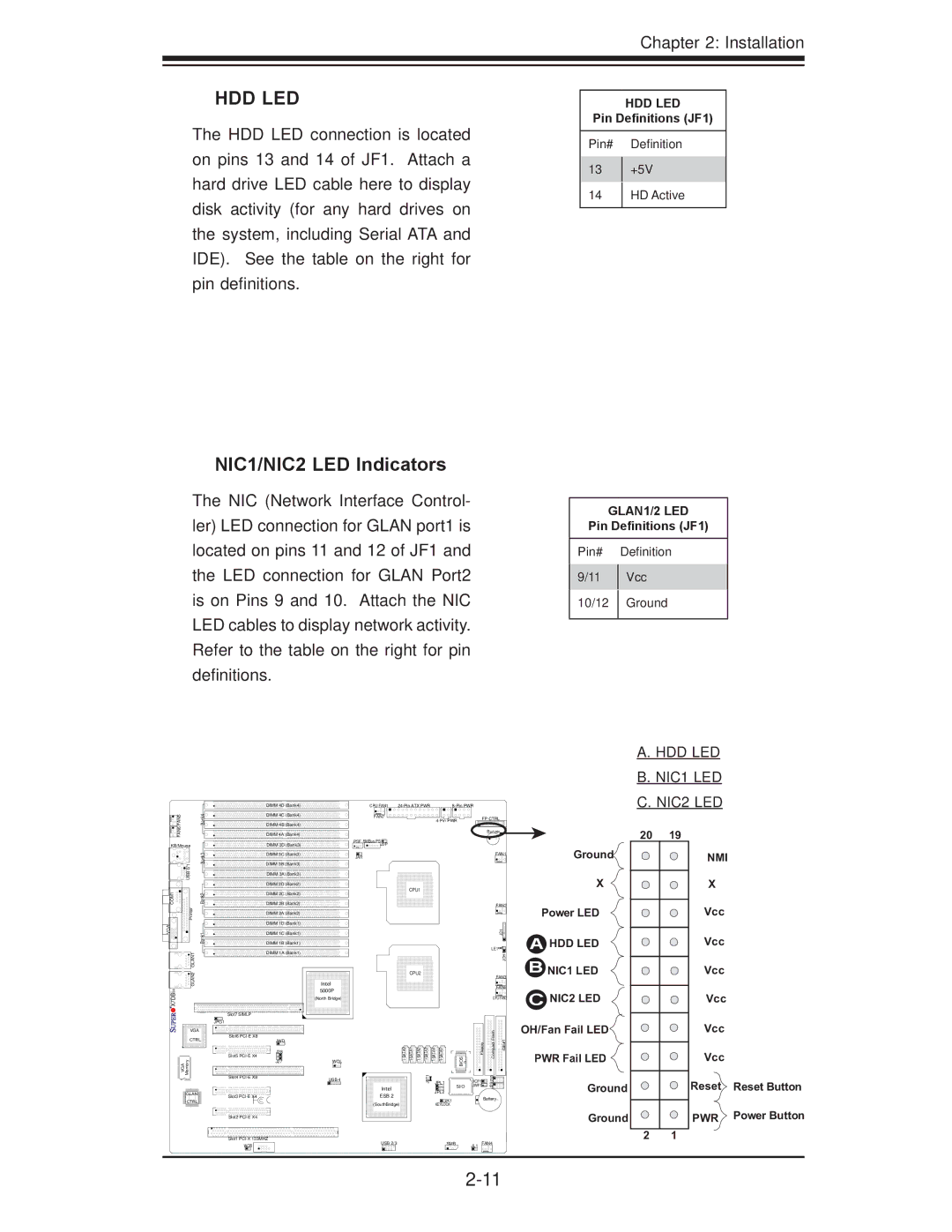
The HDD LED connection is located on pins 13 and 14 of JF1. Attach a hard drive LED cable here to display disk activity (for any hard drives on the system, including Serial ATA and IDE). See the table on the right for pin definitions.
NIC1/NIC2 LED Indicators
The NIC (Network Interface Control- ler) LED connection for GLAN port1 is located on pins 11 and 12 of JF1 and the LED connection for GLAN Port2 is on Pins 9 and 10. Attach the NIC LED cables to display network activity. Refer to the table on the right for pin definitions.
|
| DIMM 4D (Bank4) | CPU FAN1 |
| ||
FAN5 | Bank4 | DIMM 4C (Bank4) | FAN7 |
|
| FP CTRL |
|
| DIMM 4B (Bank4) |
|
| ||
FAN6 |
|
|
|
|
| |
| DIMM 4A (Bank4) |
|
|
| Buzzer | |
|
|
|
|
|
HDD LED
Pin Definitions (JF1)
Pin# Definition
13+5V
14HD Active
GLAN1/2 LED
Pin Definitions (JF1)
Pin# Definition
9/11 | Vcc | |
10/12 | Ground | |
|
|
A. HDD LED
B. NIC1 LED
C. NIC2 LED
20 | 19 |
KB/Mouse
| Bank3 |
| USB 0/1 |
COM1 | Bank2 |
| Printer |
VGA | Bank1 |
| GLAN1 |
DIMM 3D (Bank3)
DIMM 3C![]() (Bank3)
(Bank3)
DIMM 3B![]() (Bank3)
(Bank3)
DIMM 3A (Bank3)
DIMM 2D![]() (Bank2)
(Bank2)
DIMM 2C (Bank2)
DIMM 2B![]() (Bank2)
(Bank2)
DIMM 2A![]() (Bank2)
(Bank2)
DIMM 1D![]() (Bank1)
(Bank1)
DIMM 1C![]() (Bank1)
(Bank1)
DIMM 1B![]() (Bank1)
(Bank1)
DIMM 1A![]() (Bank1)
(Bank1)
PSF SMBus PSJ3P
JAR
CPU1
FAN1
FAN2
JD1![]()
LE1 |
JOH1 |
Ground
X
Power LED
AHDD LED
B |
NMI |
X |
Vcc |
Vcc
GLAN2 |
| |
X7DBi+ |
| |
| Slot7 SIMLP | |
| JPG1 | |
VGA |
| |
CTRL | Slot6 | |
| ||
VGA Memory | Slot5 | |
Slot4 | ||
| ||
GLAN | Slot3 | |
| ||
CTRL |
| |
| Slot2 |
CPU2
Intel 5000P
(North Bridge)
JWD
J28 |
| BIOS | ||
J27 | WOL |
|
|
|
USB 4 | JBT1 | JPL1 |
Intel |
| SI/O |
| JPL2 | |
ESB 2 |
| |
| JK1 | |
(SouthBridge) |
| |
| KEYLOCK |
|
| FAN3 |
|
| FAN8 |
| CPU FAN2 | |
Floppy | Compact Flash | IDE#1 |
JCF1 | J29J30 |
|
JWF1 |
| |
Battery | ||
NIC1 LED |
C NIC2 LED |
OH/Fan Fail LED
PWR Fail LED
Ground
Ground
Vcc
Vcc
Vcc
Vcc
Reset Reset Button
PWR | Power Button |
|
Slot1 | USB 2/3 | SMB |
| FAN4 |
WOR | JL1 |
2 1