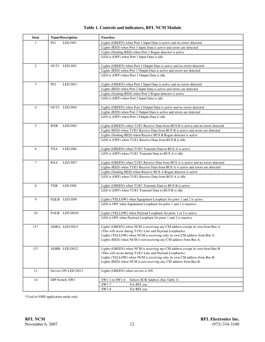
Table 1. Controls and indicators, RFL NCM Module

Item

Name/Description

1

IN1

LED DS1


2

OUT1

LED DS2


3

IN2

LED DS3


4

OUT2

LED DS4


5

RXB

LED DS5


6

TXA

LED DS6


7

RXA

LED DS7

8

TXB

LED DS8


9

EQLB

LED DS9

10PALB LED DS10

11* ADRA LED DS11

12*

ADRB LED DS12

13Service ON LED DS13

14DIP Switch, SW1

*Used in NMS application mode only.

Function

Lights (GREEN) when Port 1 Input Data is active and no errors detected Lights (RED) when Port 1 Input Data is active and errors are detected Lights (flashing RED) when Port 1 Rogue detector is active

LED is (OFF) when Port 1 Input Data is idle

Lights (GREEN) when Port 1 Output Data is active and no errors detected Lights (RED) when Port 1 Output Data is active and errors are detected LED is (OFF) when Port 1 Output Data is idle

Lights (GREEN) when Port 2 Input Data is active and no errors detected Lights (RED) when Port 2 Input Data is active and errors are detected Lights (flashing RED) when Port 2 Rogue detector is active

LED is (OFF) when Port 2 Input Data is idle

Lights (GREEN) when Port 2 Output Data is active and no errors detected Lights (RED) when Port 2 Output Data is active and errors are detected LED is (OFF) when Port 2 Output Data is idle

Lights (GREEN) when T1/E1 Receive Data from BUS B is active and no errors detected Lights (RED) when T1/E1 Receive Data from BUS B is active and errors are detected Lights (flashing RED) when Receive BUS B Rogue detector is active

LED is (OFF) when T1/E1 Receive Data from BUS B is idle

Lights (GREEN) when T1/E1 Transmit Data to BUS A is active

LED is (OFF) when T1/E1 Transmit Data to BUS A is idle

Lights (GREEN) when T1/E1 Receive Data from BUS A is active and no errors detected Lights (RED) when T1/E1 Receive Data from BUS A is active and errors are detected Lights (flashing RED) when Receive BUS A Rogue detector is active

LED is (OFF) when T1/E1 Receive Data from BUS A is idle

Lights (GREEN) when T1/E1 Transmit Data to BUS B is active

LED is (OFF) when T1/E1 Transmit Data to BUS B is idle

Lights (YELLOW) when Equipment Loopback for ports 1 and 2 is active LED is OFF when Equipment Loopback for ports 1 and 2 is inactive

Lights (YELLOW) when Payload Loopback for ports 1 or 2 is active LED is OFF when Payload Loopback for ports 1 and 2 is inactive

Lights (GREEN) when NCM is receiving any CM address except its own from Bus A. (This will occur during T1/E1 Line and Payload Loopbacks)

Lights (YELLOW) when NCM is receiving only its own CM address from Bus A. Lights (RED) when NCM is not receiving any CM address from Bus A.

Lights (GREEN) when NCM is receiving any CM address except its own from Bus B. (This will occur during T1/E1 Line and Payload Loopbacks)

Lights (YELLOW) when NCM is receiving only its own CM address from Bus B. Lights (RED) when NCM is not receiving any CM address from Bus B.

Lights (GREEN) when service is ON

SW1-1 to SW1-6 Selects SCB Address (See Table 3)

SW1-7

For RFL use

SW1-8

For RFL use

RFL NCM


RFL Electronics Inc.

November 6, 2007

12

(973) 334-3100

Page 12
Image 12
RF-Link Technology Network Communications Module manual Controls and indicators, RFL NCM Module

Network Communications Module, RFL NCM specifications

RF-Link Technology has emerged as a significant player in the realm of wireless communication, and one of its standout offerings is the RFL NCM (Network Communications Module). This module is designed to facilitate efficient and reliable data transmission in a variety of applications, making it a versatile solution for both industrial and commercial needs.

The RFL NCM is built on advanced RF technologies that support multiple communication protocols, ensuring compatibility with different systems and devices. One of its main features is its exceptional range. The module is capable of transmitting data over long distances, making it ideal for applications where devices are spread out. This long-range capability is essential for remote monitoring and control tasks, such as in smart agriculture, environmental monitoring, and industrial automation.

Another defining characteristic of the RFL NCM is its low power consumption. The module employs energy-efficient communication methods, enabling devices to operate for extended periods without frequent battery replacements. This makes it particularly useful in applications where power availability is limited or where continuous operation is required without maintenance interruptions.

The RFL NCM supports a variety of communication protocols, including LoRa, Zigbee, and MQTT, providing flexibility for developers and integrators to choose the most suitable technology for their specific applications. Its robust design ensures resilience in various operating conditions, including extreme temperatures and potential environmental hazards like moisture and dust.

Ease of integration is another strong point of the RFL NCM. With extensive documentation and support, developers can quickly incorporate the module into their existing systems. It also features built-in security protocols to safeguard data during transmission, which is particularly important in today’s increasingly connected world where data breaches are a growing concern.

The RFL NCM is not just about performance; it inherently supports scalability, allowing users to expand their network as their needs grow, whether that's adding more sensors to a monitoring system or integrating additional devices in a smart home. This commitment to both performance and adaptability makes the RFL NCM an attractive option for developers looking to harness the power of RF communications.

In summary, the RF-Link Technology RFL NCM stands out due to its long-range capabilities, low power consumption, support for multiple communication protocols, and robust integration features. With applications across various sectors, including industrial, commercial, and residential, this module promises to enhance connectivity and streamline operations in an increasingly wireless world.