MVP-TDS LED Indicators
The two LED indicators indicate the battery and communication status:
LED Pattern Indicators for the MVP-TDS
LED | Left - Battery Status | Right - Comm. Status | |
|
|
|
|
| TDS only | MVP in Cradle |
|
|
|
|
|
Solid Bright | TDS batteries are fully charged | MVP batteries are fully | MVP panel is docked and |
|
| charged | communicating |
|
|
|
|
Flashing Bright | TDS batteries are charging | MVP batteries are | N/A |
(Slow) |
| charging |
|
|
|
|
|
Flashing Bright | N/A | N/A | MVP panel is docked but not |
(Fast) |
|
| communicating |
|
|
|
|
Solid Dim | TDS receiving power but con- | No batteries within the | MVP panel is NOT docked |
| tains no batteries in cradle | MVP | and NOT communicating |
|
|
|
|
Installation
Interface Connector Pins and Functions
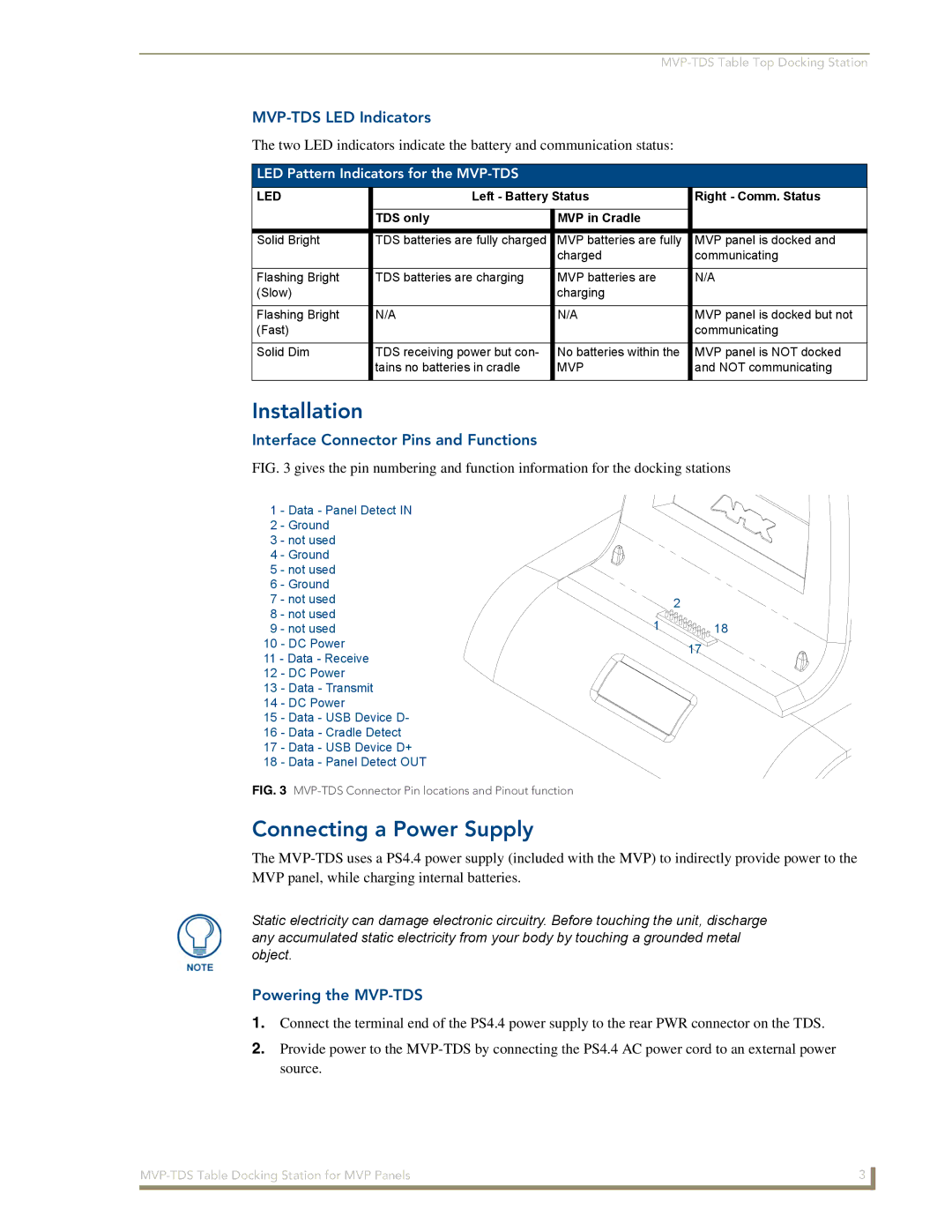
FIG. 3 gives the pin numbering and function information for the docking stations
1 | - Data - Panel Detect IN |
|
| |
2 | - Ground |
|
| |
3 | - not used |
|
| |
4 | - Ground |
|
| |
5 | - not used |
|
| |
6 | - Ground |
|
| |
7 | - not used |
| 2 | |
8 | - not used |
| ||
1 | 18 | |||
9 | - not used | |||
10 | - DC Power |
| 17 | |
11 - Data - Receive |
| |||
|
| |||
12 | - DC Power |
|
| |
13 | - Data - Transmit |
|
| |
14 | - DC Power |
|
| |
15 | - Data - USB Device D- |
|
| |
16 | - Data - Cradle Detect |
|
| |
17 | - Data - USB Device D+ |
|
| |
18 | - Data - Panel Detect OUT |
|
| |
FIG. 3 MVP-TDS Connector Pin locations and Pinout function
Connecting a Power Supply
The
Static electricity can damage electronic circuitry. Before touching the unit, discharge any accumulated static electricity from your body by touching a grounded metal object.
Powering the MVP-TDS
1.Connect the terminal end of the PS4.4 power supply to the rear PWR connector on the TDS.
2.Provide power to the
3 | |
|
|
