Chapter 2: Installation
SMB
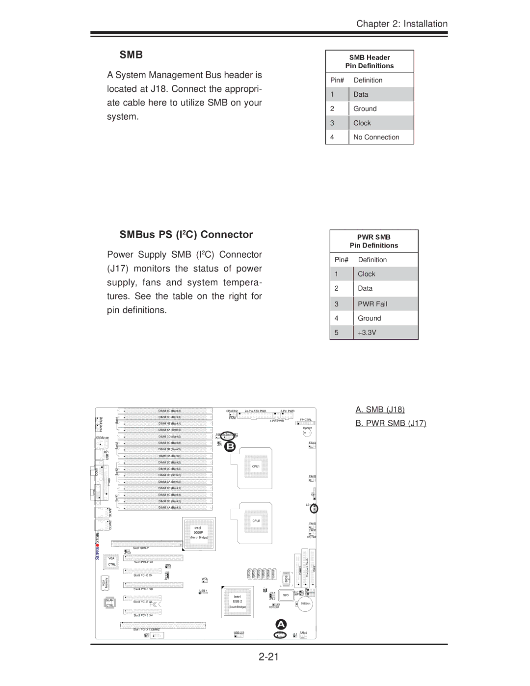
A System Management Bus header is located at J18. Connect the appropri- ate cable here to utilize SMB on your system.
SMBus PS (I2C) Connector
Power Supply SMB (I2C) Connector (J17) monitors the status of power supply, fans and system tempera- tures. See the table on the right for pin definitions.
SMB Header
Pin Definitions
Pin# Definition
1Data
2Ground
3Clock
4No Connection
PWR SMB
Pin Definitions
Pin# Definition
1Clock
2Data
3PWR Fail
4Ground
5+3.3V
|
| DIMM 4D (Bank4) | CPU FAN1 |
| ||
FAN5 | Bank4 | DIMM 4C (Bank4) | FAN7 |
|
| FP CTRL |
|
|
|
| |||
|
|
|
|
| ||
FAN6 |
| DIMM 4B (Bank4) |
|
|
|
|
| DIMM 4A (Bank4) |
|
|
| Buzzer | |
|
|
|
|
|
A. SMB (J18)
B. PWR SMB (J17)
KB/Mouse
| Bank3 |
| USB 0/1 |
COM1 | Bank2 |
| Printer |
VGA | Bank1 |
DIMM 3D (Bank3)
DIMM 3C![]() (Bank3)
(Bank3)
DIMM 3B![]() (Bank3)
(Bank3)
DIMM 3A (Bank3)
DIMM 2D![]() (Bank2)
(Bank2)
DIMM 2C (Bank2)
DIMM 2B![]() (Bank2)
(Bank2)
DIMM 2A![]() (Bank2)
(Bank2)
DIMM 1D![]() (Bank1)
(Bank1)
DIMM 1C![]() (Bank1)
(Bank1)
DIMM 1B![]() (Bank1)
(Bank1)
PSF SMBus PSJ3P
JAR B
CPU1
FAN1
FAN2
JD1![]()
LE1 |
![]()
![]()
![]()
![]()
![]() GLAN2 GLAN1
GLAN2 GLAN1![]()
X7DBi+
VGA
CTRL
Memory
VGA
![]() GLAN
GLAN ![]()
![]() CTRL
CTRL ![]()
Slot7 SIMLP
JPG1
Slot6
Slot5
Slot4
Slot3
DIMM 1A![]() (Bank1)
(Bank1)
CPU2
Intel 5000P
(North Bridge)
JWD
J28 |
| BIOS | ||
J27 | WOL |
|
|
|
USB 4 | JBT1 | JPL1 |
Intel |
| SI/O |
| JPL2 | |
ESB 2 |
| |
| JK1 | |
(SouthBridge) |
| |
| KEYLOCK |
|
| JOH1 |
|
| FAN3 |
|
| FAN8 |
| CPU FAN2 | |
Floppy | Compact Flash | IDE#1 |
JCF1 | J29J30 |
|
JWF1 |
| |
Battery | ||
Slot2
A
Slot1 | USB 2/3 | SMB |
| FAN4 |
WOR | JL1 |
