APPLICATIONS_______________________________________________________________________________________
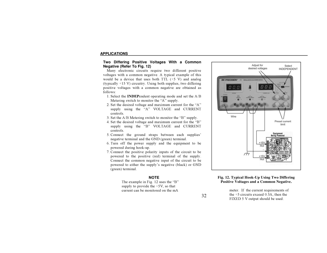
Two Differing Positive Voltages With a Common Negative (Refer To Fig. 12)
Many electronic circuits require two different positive voltages with a common negative. A typical example of this would be a device that uses both TTL (+5 V) and analog (typically +15 V) circuitry. Using both supplies, two differing positive voltages with a common negative are obtained as follows:
1.Select the INDEPendent operating mode and set the A/B Metering switch to monitor the “A” supply.
2.Set the desired voltage and maximum current for the “A” supply using the “A” VOLTAGE and CURRENT controls.
3.Set the A/B Metering switch to monitor the “B” supply.
4.Set the desired voltage and maximum current for the “B” supply using the “B” VOLTAGE and CURRENT controls.
5.Connect the ground straps between each supplies’ negative terminal and the GND (green) terminal.
6.Turn off the power supply and the equipment to be powered during
7.Connect the positive polarity inputs of the circuit to be powered to the positive (red) terminal of the supply. Connect the common negative input of the circuit to be powered to either the supply’s negative (black) or GND (green) terminal.
NOTE
The example in Fig. 12 uses the “B” supply to provide the +5V, so that current can be monitored on the mA
Fig. 12. Typical Hook-Up Using Two Differing Positive Voltages and a Common Negative.
meter. If the current requirements of
32 the +5 circuits exceed 0.5A, then the FIXED 5 V output should be used.
