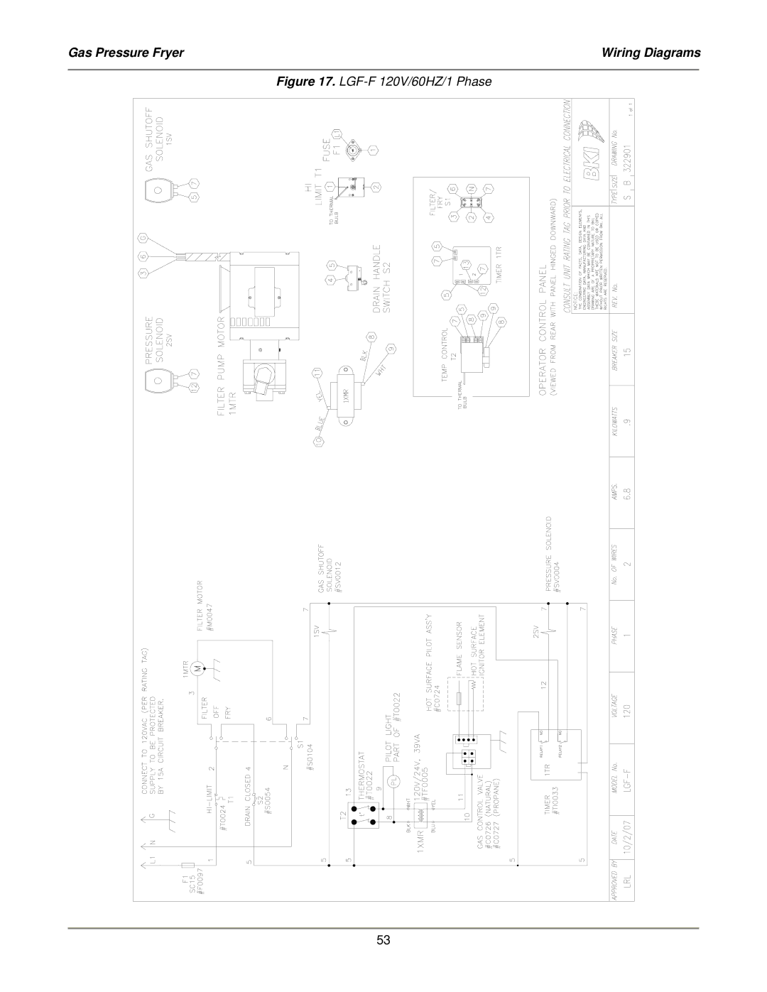
Manuals
/
Bakers Pride Oven
/
Kitchen Appliance
/
Fryer
Bakers Pride Oven
LGF-FC Gas Pressure Fryer, Wiring Diagrams, LGF-F120V/60HZ/1 Phase
Models:
LGF-F
LGF-FC
LGF
1
55
60
60
Download
60 pages
45.36 Kb
52
53
54
55
56
57
58
59
<
>
Install
Wiring Diagrams
Replacement Parts
Maintenance
8A, B, C, D preset buttons Beeper Display
Assembly #
LGF-F120V/60HZ/1 Phase
Keep The Floor Around Your Fryer Clean Of
Controls and Indicators
How to
Page 55
Image 55
Gas Pressure Fryer
Wiring Diagrams
Figure 17.
LGF-F
120V/60HZ/1 Phase
53
Page 54
Page 56
Page 55
Image 55
Page 54
Page 56
Contents
Serial Numbers 137733 and higher
Gas Pressure Fryer
FOR YOUR SAFETY
Warranty Information
LIMITED ONE YEAR WARRANTY
REPLACEMENT PARTS
Table of Contents
Table of Contents
Gas Pressure Fryer
Safety Signs and Messages
Safety
Introduction
Equipotential ground plane
Specific Precautions
Full Disconnection
Beware of High Voltage
Do Not Store Or Use Anything Flammable Near
The Fryer
Use Gas Safely--Avoid Danger
Keep The Casters Locked
Keep The Floor Around Your Fryer Clean Of
Keep The Lid Closed When The Fryer Is Not In Use
Shortening
Closing The Fryer
Always Tighten The Spin Handle When Closing
Seal The Safety Valve Properly
Always Make Sure The Lid Hook Is Latched When
Protect Children
Keep Safety Labels Clean and in Good Condition
Keep Away From The Vent
Keep this manual with the Equipment
Know your responsibilities as an Employer
Be Prepared for Emergencies
Do Not Smoke Near The Fryer
Gas Pressure Fryer
Safety Labels
Introduction
Introduction
Gas Pressure Fryer
Installation
Installation
Gas Pressure Fryer
Operation
Controls and Indicators
Function
Item Description
Item Description
8A, B, C, D preset buttons Beeper Display
Function
LGF and LGF-FOperation
Care of the Shortening
Start-UpLGF and LGF-F
DISPLAY
Cooking LGF and LGF-F
MODE DESCRIPTION
11.Slowly open the lid
System Programming
LGF-FCOperation
ACTION
Gas Pressure Fryer
Operation
STEP
Product Programming
STEP
Gas Pressure Fryer
Operation
COMMENTS
DISPLAY
STEP
ACTION
COMMENTS
Cooking LGF-FC
Start-Up LGF-FC
12.Slowly open the lid
French Fries
Recipes
Fried Onion Rings
Potato Wedges
Cube Or Minute Steaks
Whole Turkey 12 to 14 pounds
Whole Duckling
Pork Chops
Normal Shutoff
Operation After Gas or Power Outage
Maintenance
Maintenance
Gas Pressure Fryer
Description
Replacement Parts
Assembly #
Assemblies
Figure 3. Lid/Arm Assembly, AN3211350S Sheet 1 of
Replacement Parts
Gas Pressure Fryer
Figure 3. Lid/Arm Assembly, AN3211350S Sheet 2 of
Replacement Parts
Gas Pressure Fryer
Figure 3. Lid/Arm Assembly, AN3211350S Sheet 3 of
Replacement Parts
Gas Pressure Fryer
Figure 3. Lid/Arm Assembly, AN3211350S Sheet 4 of
Replacement Parts
Gas Pressure Fryer
PART #
Replacement Parts
Gas Pressure Fryer
ITEM #
PART #
ITEM #
DESCRIPTION
Figure 5. Drain/Motor/Piping Assembly
Replacement Parts
Gas Pressure Fryer
Table 5. Drain/Motor/Piping Assembly Parts
Figure 6. Burner Tray Assembly
Replacement Parts
Gas Pressure Fryer
Gas Pressure Fryer
Gas Pressure Fryer
Replacement Parts
Figure 7. Control/Insulation Panel LGF & LGF-F
Table 7. Control/Insulation Panel LGF & LGF-FParts
Gas Pressure Fryer
Replacement Parts
Figure 8. Control/Insulation Panel LGF -FC
Table 8. Control/Insulation Panel LGF -FCParts
H0010
ITEM #
PART #
DESCRIPTION
Figure 10. Oil Vat Assembly AN32112800
Replacement Parts
Gas Pressure Fryer
F0067
ITEM #
PART #
DESCRIPTION
FT0235
ITEM #
PART #
DESCRIPTION
B0996
ITEM #
PART #
DESCRIPTION
ITEM #
DRAIN VALVE REPLACEMENT
Figure 14. Drain Valve & Plugs SB1999S
Table 14. Drain Valve & Plugs SB1999S Parts
Description
Accessories
Accessory #
Item #
Figure #
Components
Component #
Description
Page #
Wiring Diagrams
Wiring Diagram
Diagram #
Figure 17. LGF-F120V/60HZ/1 Phase
Wiring Diagrams
Gas Pressure Fryer
Figure 18. LGF-FC120V/60HZ/1 Phase
Wiring Diagrams
Gas Pressure Fryer
Figure 19. LGF-FC220V/50HZ/1 Phase
Wiring Diagrams
Gas Pressure Fryer
Figure 20. LGF-FC220V/60HZ/1 Phase
Wiring Diagrams
Gas Pressure Fryer
Figure 21. LGF-FC240V/50HZ/1 Phase
Wiring Diagrams
Gas Pressure Fryer