BBU 15 HE specifications
The Baxi Potterton BBU 15 HE is a high-efficiency boiler designed to offer exceptional performance for both heating and hot water needs in residential settings. Known for its robust build quality and user-friendly features, this model is particularly favored for its versatility and reliability in various home environments.One of the standout features of the Baxi Potterton BBU 15 HE is its compact size, making it suitable for installation in smaller spaces. Despite its small footprint, it delivers impressive outputs, making it ideal for homes with moderate heating demands. The boiler’s high efficiency rating ensures reduced energy consumption, leading to lower utility bills and a smaller carbon footprint.
Equipped with a powerful heat exchanger, the BBU 15 HE maximizes heat transfer, ensuring that households receive optimum warmth and hot water. With an output capacity of 15 kW, it can effectively heat a variety of living spaces while providing hot water on demand, making it a practical choice for families.
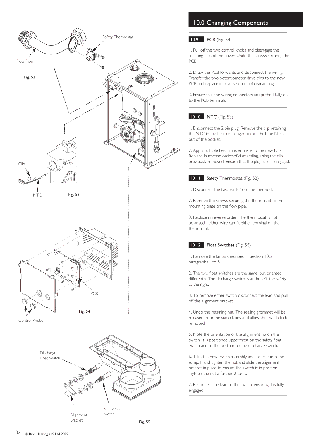
The boiler incorporates a number of advanced technologies that enhance its performance. One such feature is the built-in frost protection, which helps prevent the system from freezing during colder months. Additionally, the BBU 15 HE is designed for easy maintenance, featuring a simple access point for servicing, which can prolong the boiler’s lifespan and improve overall efficiency.
Safety is a top priority in any boiler installation, and the Baxi Potterton BBU 15 HE includes multiple safety features such as a pre-set temperature limit that prevents overheating and a pressure relief valve to manage excessive pressure within the system. These elements contribute to a safer home environment, providing peace of mind for homeowners.
Furthermore, the boiler is designed to operate quietly, minimizing disruptions in the home when heating systems are active. This is an important factor for many households where comfort is a priority.
In summary, the Baxi Potterton BBU 15 HE is a compact, efficient, and reliable boiler that provides an optimal solution for home heating and hot water needs. Its advanced features, safety systems, and user-friendly design make it a popular choice among homeowners, ensuring a cozy and comfortable living environment. Whether for a new installation or a replacement unit, this boiler stands out as a highly effective option in the market.

