Manuals
/
Beckett
/
Household Appliance
/
Burner
Beckett
CF2500
manual
Typical Wiring 7505P
Models:
CF2500
1
14
24
24
Download
24 pages
59.98 Kb
11
12
13
14
15
16
17
18
Install
Wire the Burner
Warranty
Dimension
Maintenance
Adjusting Plate Assembly
Initial Air Settings
Replacement Parts
Safety
Professional Service Required
Page 14
Image 14
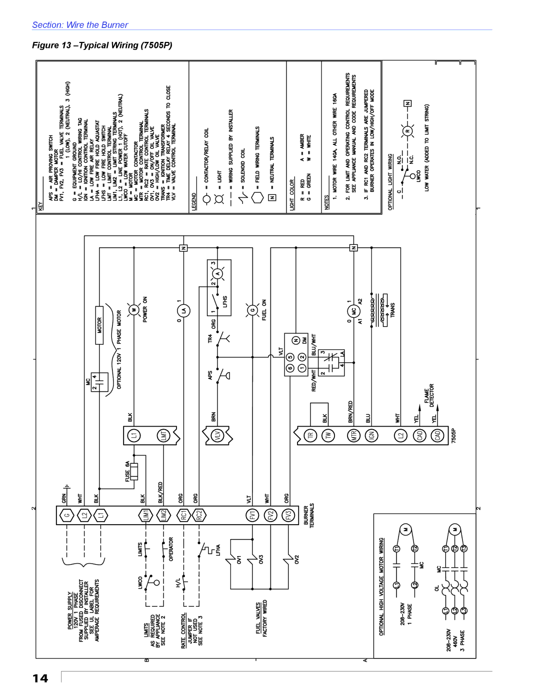
Section: Wire the Burner
Figure 13
–Typical
Wiring (7505P)
14
Page 13
Page 15
Page 14
Image 14
Page 13
Page 15
Contents
Potential for Fire, Smoke and Asphyxiation Hazards
To the Homeowner or Equipment Owner
Contents
Frozen Plumbing Water Damage Hazard
General Information
Hazard Definitions
Fuel Supply Oil Supply Pressure Control Required
Pre-installation Checklist
Clearances
Vent System
Nozzle Pressure Correct Nozzle and Flow Rate Required
Electrical Supply
Fire, Smoke & Asphyxiation Hazard
Verify Air Tube
Air Tube Combination Codes
Protect the Air Tube From Overheating
Mount the Burner
Dust and Moisture Protect Against Dust
Mount Flanges on Air Tube
Install Nozzle Line Assembly
Install Nozzle
Check Electrode Settings Maintain Electrode Specifications
Mount Air Tube to Burner
Set Dimension Z
Insert Burner
Connect Fuel Lines
Psig to
Electrical Shock Hazard
Wire the Burner
Incorrect Wiring Will Result in Improper Control Operation
Fire or Explosion Hazard
Standby
Cad Cell Resistance Measurement
Typical Wiring 7505P
Typical Burner Sequence of Operation RM7897A Control
Typical Burner Sequence Operation RM7897A
Keep Service Access Covers Securely Installed
Professional Installation Service Required
Do Not Bypass Safety Controls
Initial Head Position
Dimension
Adjusting Plate Assembly
Initial Air Settings
Damper Motor with Cover
Set Appliance Limit Controls
Professional Service Required
Start the Burner
Prepare the Fuel Unit for Air Venting
If burner stops during venting
Set High-fire Air
Set Low-fire Air
If burner stops after flame established
Monthly Maintenance by owner
Perform Regular Maintenance
Annual Professional Service Required
Replacement Parts
Description CF2500 Part No CF3500 Part No
Flange a
Limited Warranty Information
Top
Page
Image
Contents