Table 2 - Air Tube Capacity Versus Firebox Pressure
Maximum Firing Rate GPH
|
| Firebox | No | 10% Turndown | |
Model | Tube | Pressure | Reserve | ||
(GPH) | |||||
|
| (In W.C.) | Air | ||
|
|
| |||
|
| 0.0 | 25.0 | 22.5 | |
CF2500& CF2500A |
| 0.2 | 24.8 | 22.3 | |
KP | 0.4 | 24.6 | 22.3 | ||
| |||||
| 0.6 | 24.5 | 22.1 | ||
|
| ||||
|
| 0.8 | 24.3 | 21.9 | |
|
| 1.0 | 24.1 | 21.7 | |
|
| 0.0 | 35.0 | 31.5 | |
CF3500A |
| 0.2 | 33.5 | 30.2 | |
KM/ | 0.4 | 32.0 | 28.8 | ||
| |||||
| KR | 0.6 | 30.2 | 27.2 | |
|
| 0.8 | 28.8 | 25.9 | |
|
| 1.0 | 27.1 | 24.4 |
Note: 10% turndown indicates sufficient reserve air to reduce the CO2 in the flue to 90% of its value.
Note: The above ratings may vary 5% due to variations in actual job conditions.
Stray Light
Protect Against Stray Light Lockout. Failure to follow these instructions could cause loss of burner
operation resulting in no heat, an unplanned process interruption, work stoppage and the potential for frozen plumbing or other cold weather property damage.
○The control must detect a dark,
○Shield the burner view window from direct exposure to intense light.
Dust and Moisture
Protect Against Dust and
Moisture
Wet, dusty environments could lead to blocked air passages, corrosion damage to components, impaired combustion performance and result in asphyxiation, explosion or fire.
y This burner is designed for clean, dry installations.
y Electrical controls are not protected against rain or sprayed water.
y Keep the installation clear of dust, dirt, corrosive vapors, and moisture.
y Protective covers and more frequent maintenance may be required.
Section: Mount the Burner
Mount the Burner
Protect the Air Tube From
Overheating
Overheating could cause damage to the air tube and other combustion components leading to equipment malfunction and impaired combustion performance.
yThe end of the air tube must not extend into the combustion chamber unprotected unless it has been
yPosition the end of the air tube 1/4” back from
flush with the refractory inside entry wall to prevent damage from overheating.
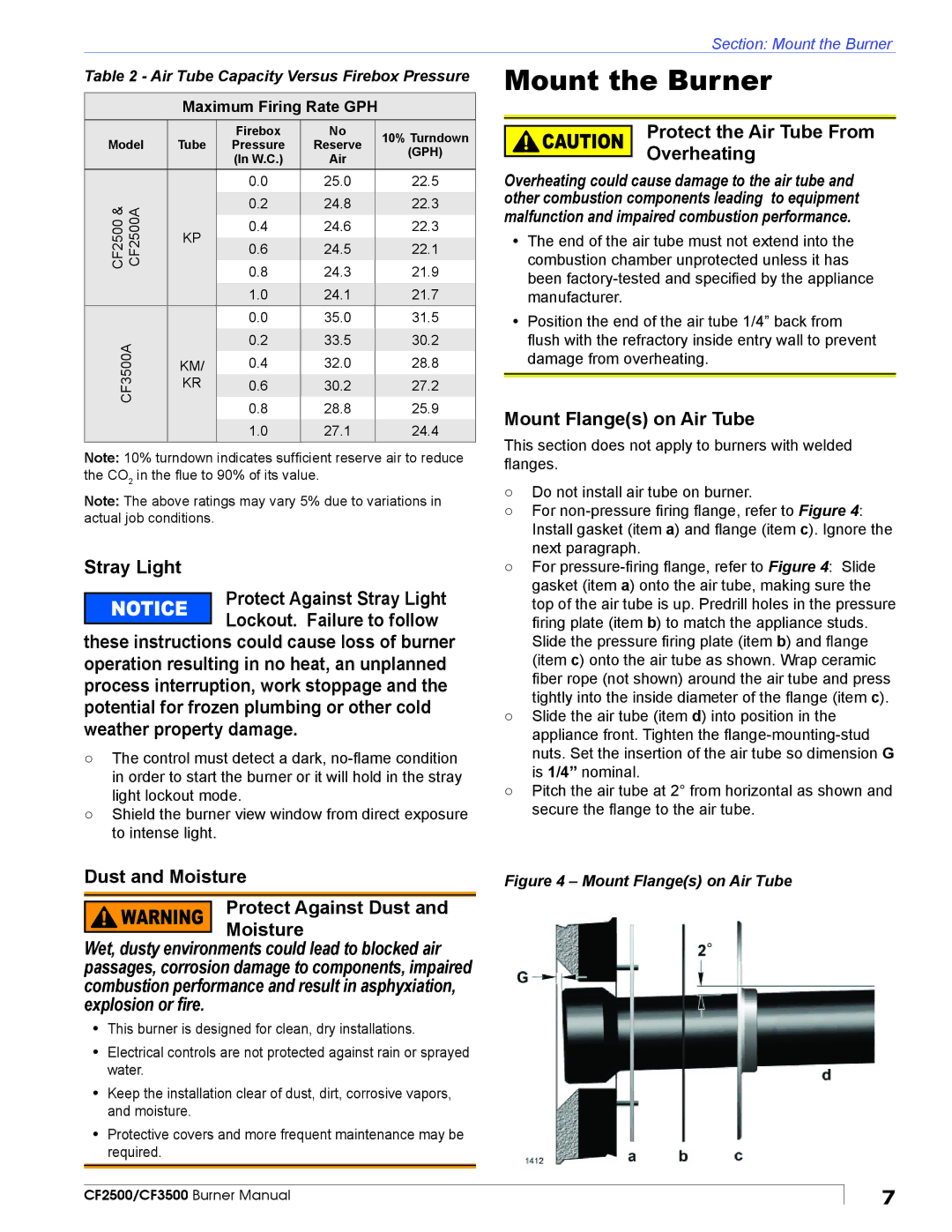
Mount Flange(s) on Air Tube
This section does not apply to burners with welded flanges.
○Do not install air tube on burner.
○For
○For
○Slide the air tube (item d) into position in the appliance front. Tighten the
○Pitch the air tube at 2° from horizontal as shown and secure the flange to the air tube.
Figure 4 – Mount Flange(s) on Air Tube
CF2500/CF3500 Burner Manual
7