1.1.2 Safety Check after Servicing

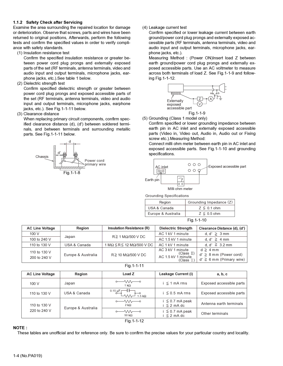
Examine the area surrounding the repaired location for damage or deterioration. Observe that screws, parts and wires have been returned to original positions, Afterwards, perform the following tests and confirm the specified values in order to verify compli- ance with safety standards.

(1)Insulation resistance test

Confirm the specified insulation resistance or greater be- tween power cord plug prongs and externally exposed parts of the set (RF terminals, antenna terminals, video and audio input and output terminals, microphone jacks, ear- phone jacks, etc.).See table 1 below.

(2)Dielectric strength test

Confirm specified dielectric strength or greater between power cord plug prongs and exposed accessible parts of the set (RF terminals, antenna terminals, video and audio input and output terminals, microphone jacks, earphone jacks, etc.). See Fig.1-1-11 below.

(3)Clearance distance

When replacing primary circuit components, confirm spec- ified clearance distance (d), (d') between soldered termi- nals, and between terminals and surrounding metallic parts. See Fig.1-1-11 below.

d

d' Chassis

Power cord primary wire

Fig.1-1-8

(4)Leakage current test

Confirm specified or lower leakage current between earth ground/power cord plug prongs and externally exposed ac- cessible parts (RF terminals, antenna terminals, video and audio input and output terminals, microphone jacks, ear- phone jacks, etc.).

Measuring Method : (Power ON)Insert load Z between earth ground/power cord plug prongs and externally ex- posed accessible parts. Use an AC voltmeter to measure across both terminals of load Z. See Fig.1-1-9 and follow- ing Fig.1-1-12.


a

b

Externally

Z

A

c


exposed

V


accessible part


Fig.1-1-9

(5)Grounding (Class 1 model only)

Confirm specified or lower grounding impedance between earth pin in AC inlet and externally exposed accessible parts (Video in, Video out, Audio in, Audio out or Fixing screw etc.).Measuring Method:

Connect milli ohm meter between earth pin in AC inlet and exposed accessible parts. See Fig.1-1-10 and grounding specifications.

AC inlet

Exposed accessible part

Earth pin

MIlli ohm meter

Grounding Specifications


Region

Grounding Impedance (Z)

USA & Canada

Z


0.1 ohm


Europe & Australia

Z


0.5 ohm


Fig.1-1-10


AC Line Voltage

Region


( )

Dielectric Strength


Clearance Distance (d), (d')

Insulation Resistance R


100 V

Japan

R


1 M /500 V DC

AC 1 kV 1 minute


d, d'


3 mm


100 to 240 V


AC 1.5 kV 1 minute


d, d'


4 mm


110 to 130 V

USA & Canada

1 M


R


12 M /500 V DC

AC 1 kV 1 minute


d, d'


3.2 mm


110 to 130 V


AC 3 kV 1 minute


d


4 mm

Europe & Australia

R

10 M /500 V DC


(Class

)

d'


8 mm (Power cord)


200 to 240 V


AC 1.5 kV 1 minute


d'


6 mm (Primary wire)


(Class

)


Fig.1-1-11


AC Line Voltage

Region


Load Z

Leakage Current (i)


a, b, c

100 V

Japan


1


i


1 mA rms


Exposed accessible parts


110 to 130 V

USA & Canada

0.15


i


0.5 mA rms


Exposed accessible parts


1.5


110 to 130 V


i


0.7 mA peak


Antenna earth terminals

Europe & Australia


2


i


2 mA dc


220 to 240 V


i


0.7 mA peak


Other terminals


50


i


2 mA dc


Fig.1-1-12

NOTE :

These tables are unofficial and for reference only. Be sure to confirm the precise values for your particular country and locality.

1-4 (No.PA019)

Page 4
Image 4
Belkin DLA-HD2KE, DLA-HD2KU service manual Safety Check after Servicing, AC Line Voltage Region

DLA-HD2KU, DLA-HD2KE specifications

The Belkin DLA-HD2KE and DLA-HD2KU represent the forefront of advanced HDMI splitters, designed to cater to the evolving needs of home entertainment and professional setups. These devices are essential for users who wish to transmit high-definition audio and video signals across multiple displays without any degradation in quality.

One of the standout features of the DLA-HD2KE and DLA-HD2KU is their capability to support resolutions up to 4K at 60Hz. This ensures that users can enjoy stunning visuals with rich colors and sharp details, making these splitters an ideal choice for modern televisions, projectors, and monitors. The 4K support is complemented by support for HDR (High Dynamic Range) content, enhancing the brightness and contrast levels for a more immersive viewing experience.

Both models come equipped with EDID (Extended Display Identification Data) management, allowing for seamless communication between the source device and the connected displays. This feature eliminates compatibility issues that can arise when using different display devices, ensuring consistent video output.

The DLA-HD2KE and DLA-HD2KU utilize advanced HDMI technology that implements HDCP 2.2 compliance. This is crucial for users who want to stream content from services that require anti-piracy measures, such as Netflix and Amazon Prime. The compliance with HDCP 2.2 ensures that users won't face signal loss or interruptions during playback.

Noise reduction technology is another hallmark of these splitters. By minimizing the impact of electromagnetic interference, the DLA-HD2KE and DLA-HD2KU deliver a clear, uninterrupted signal. This is particularly beneficial in environments cluttered with various electronic devices, ensuring the integrity of your audio and video signals remains intact.

Additionally, the DLA-HD2KE model features a sleek design with a compact form factor, allowing for easy integration into any entertainment setup. The DLA-HD2KU offers a more robust user experience with enhanced connectivity options, including additional HDMI ports for users with multiple devices.

Both models come with a user-friendly installation process, offering plug-and-play functionality that eliminates the need for complicated setup procedures. Built with high-quality materials, these splitters are designed for durability and longevity, making them a reliable choice for both home users and professionals.

In summary, the Belkin DLA-HD2KE and DLA-HD2KU splitters are engineered to deliver high-quality multimedia experiences, boasting features such as 4K support, HDR compatibility, EDID management, and noise reduction technology. They are ideal solutions for those seeking to enhance their audio-visual setups, whether at home or in commercial applications.