| | CHECK | | | ORIFICE |
DESICCANT | | VALVE | | |
| ← | | | |
CARTRIDGE | | ← | |
| ← | | ← | | ← |
| | | |
| | | ← |
| ← | | | | ← |
DESICCANT | | ← | ← | ← |
← | | | | ← |
BED | | | |
| | | | PURGE |
| | | ← | |
| | | | VOLUME |
| | | | |
OIL | ← | ← | ← | ← | ← |
SEPARATOR | | | | | |
CONTROL | | | | | |
PORT | ← | ← | | ← | ← |
| |
| | | | |
| | | | ← | ← |
| ← | ← |
| ENGINE | |
| TURBO | |
← | RESERVOIR | ← |
← | ← |
SUPPLY | |
PORT | |
← | ← |
| PURGE |
| VALVE |
SUMP
EXHAUST HEATER ELEMENT
 CHECK VALVE
ASSEMBLY
DELIVERY
PORT
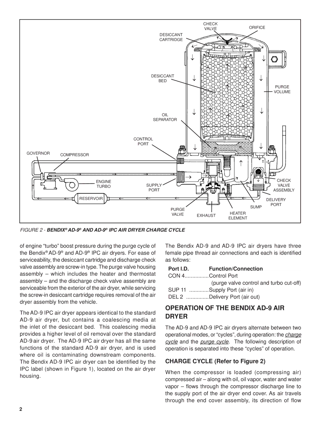
FIGURE 2 - BENDIX® AD-9®AND AD-9®IPC AIR DRYER CHARGE CYCLE
of engine “turbo” boost pressure during the purge cycle of the Bendix® AD-9®and AD-9®IPC air dryers. For ease of serviceability, the desiccant cartridge and discharge check valve assembly are screw-in type. The purge valve housing assembly – which includes the heater and thermostat assembly – and the discharge check valve assembly are serviceable from the exterior of the air dryer, while servicing the screw-in desiccant cartridge requires removal of the air dryer assembly from the vehicle.
The AD-9 IPC air dryer appears identical to the standard AD-9 air dryer, but contains a coalescing media at the inlet of the desiccant bed. This coalescing media provides a higher level of oil removal over the standard AD-9 air dryer. The AD-9 IPC air dryer has all the same functions of the standard AD-9 air dryer, and is used where oil is contaminating downstream components. The Bendix AD-9 IPC air dryer can be identified by the IPC label (shown in Figure 1), located on the air dryer housing.
The Bendix AD-9 and AD-9 IPC air dryers have three female pipe thread air connections and each is identified as follows:
Port l.D. | Function/Connection |
CON 4 | Control Port |
| (purge valve control and turbo cut-off) |
SUP 11 | Supply Port (air in) |
DEL 2 | Delivery Port (air out) |
OPERATION OF THE BENDIX AD-9 AIR DRYER
The AD-9 and AD-9 IPC air dryers alternate between two operational modes, or “cycles”, during operation: the charge cycle and the purge cycle. The following description of operation is separated into these “cycles” of operation.
CHARGE CYCLE (Refer to Figure 2)
When the compressor is loaded (compressing air) compressed air – along with oil, oil vapor, water and water vapor – flows through the compressor discharge line to the supply port of the air dryer end cover. As air travels through the end cover assembly, its direction of flow