RS422/485 SERIAL INTERFACE PLUS
DIP shunt E4 selects the pin out for the DB25 connector P3. With the
Signal |
| Name | Pin # | Mode |
GND |
| Ground | 7 |
|
RDB | RX+ | Receive Positive | 16 | Input |
RDA | RX | Receive Negative | 3 | Input |
CTSB | CTS+ | Clear To Send Positive | 13 | Input |
CTSA | CTS- | Clear To Send Negative | 5 | Input |
DSRB | DSR+ | Data Set Ready Positive | 22 | Input |
DSRA | DSR- | Data Set Ready Negative | 6 | Input |
DCDB | DCD+ | Data Carrier Detect Positive | 10 | Input |
DCDA | DCD- | Data Carrier Detect Negative | 8 | Input |
TDB | TX+ | Transmit Positive | 14 | Output |
TDA | TX- | Transmit Negative | 2 | Output |
RTSB | RTS+ | Request To Send Positive | 19 | Output |
RTSA | RTS- | Request To Send Negative | 4 | Output |
DTRB | DTR+ | Data Terminal Ready Positive | 23 | Output |
DTRA | DTR- | Data Terminal Ready Negative | 20 | Output |
|
|
|
|
|
|
|
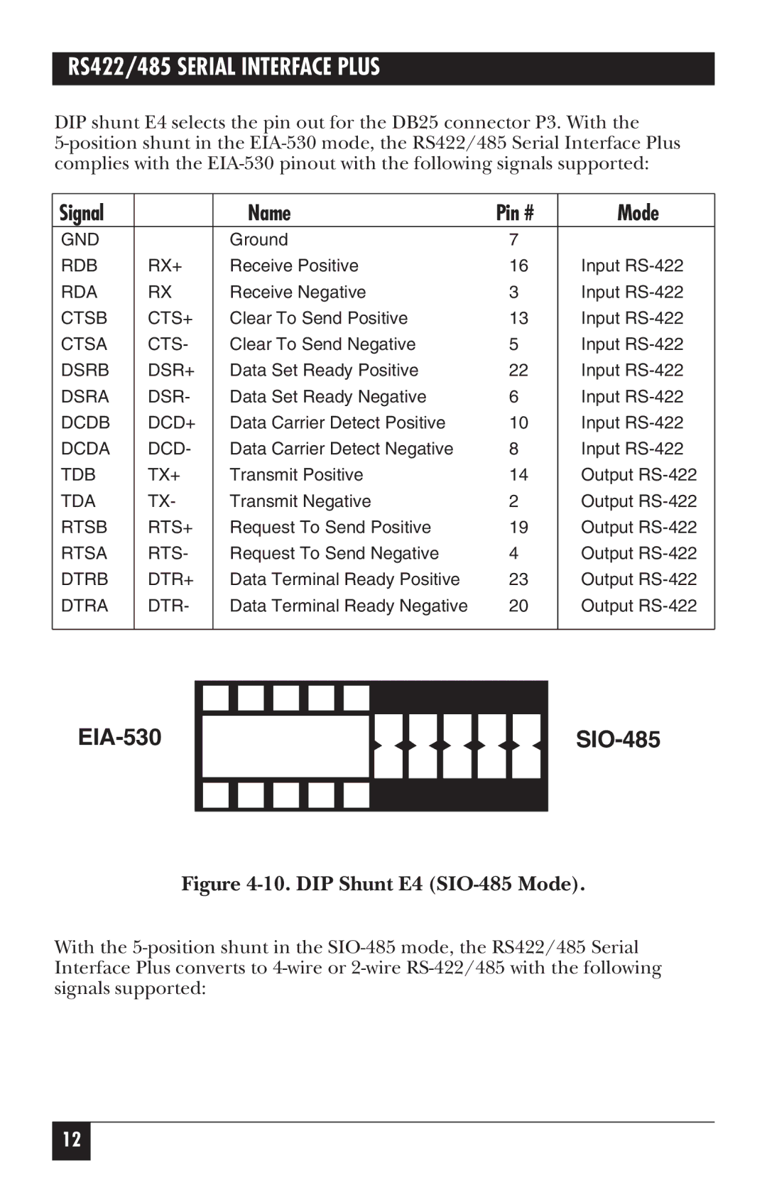
Figure 4-10. DIP Shunt E4 (SIO-485 Mode).
With the
12