Black Box IC171C manual Auto RTS

Models: IC171C

1 30
Download 30 pages 15.74 Kb
Page 15
Image 15

RS422/485 SERIAL INTERFACE PLUS

MM

SS

NN

Figure 4-4. Header E2 in Shared Mode.

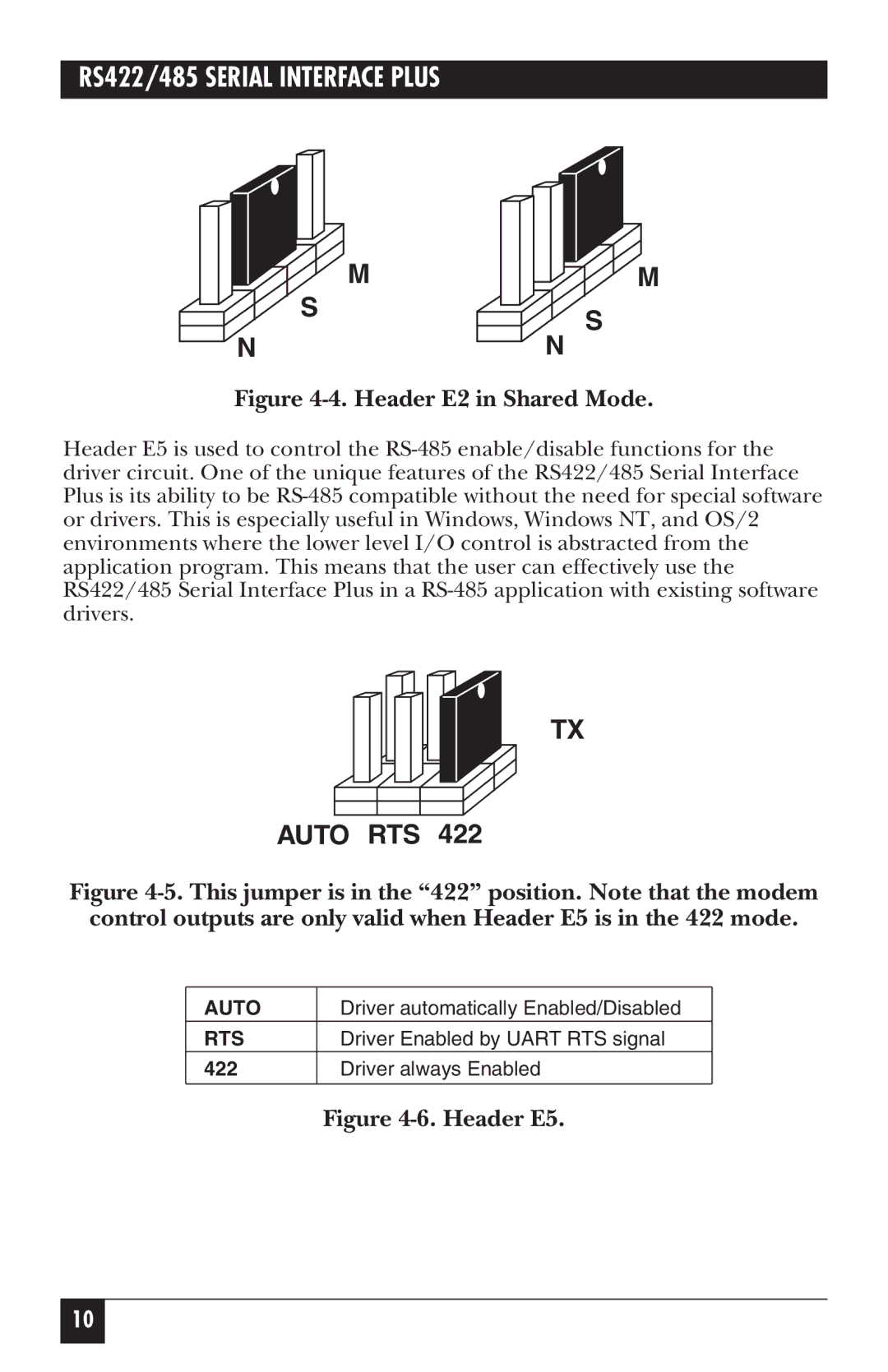
Header E5 is used to control the RS-485 enable/disable functions for the driver circuit. One of the unique features of the RS422/485 Serial Interface Plus is its ability to be RS-485 compatible without the need for special software or drivers. This is especially useful in Windows, Windows NT, and OS/2 environments where the lower level I/O control is abstracted from the application program. This means that the user can effectively use the RS422/485 Serial Interface Plus in a RS-485 application with existing software drivers.

TX

AUTO RTS 422

Figure 4-5. This jumper is in the “422” position. Note that the modem control outputs are only valid when Header E5 is in the 422 mode.

AUTO

Driver automatically Enabled/Disabled

RTS

Driver Enabled by UART RTS signal

422Driver always Enabled

Figure 4-6. Header E5.

10

Page 15
Image 15
Black Box IC171C manual Auto RTS