CHAPTER 4: Option Selection
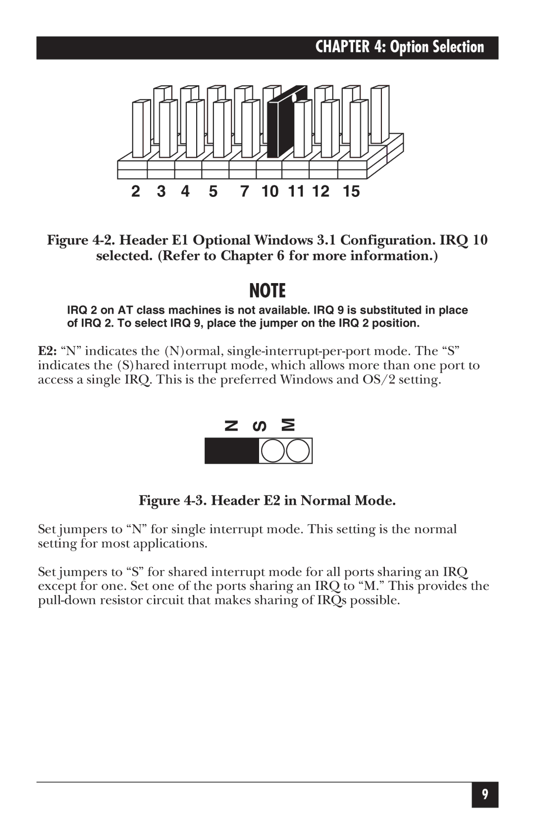
2 3 4 5 7 10 11 12 15
Figure 4-2. Header E1 Optional Windows 3.1 Configuration. IRQ 10
selected. (Refer to Chapter 6 for more information.)
NOTE
IRQ 2 on AT class machines is not available. IRQ 9 is substituted in place of IRQ 2. To select IRQ 9, place the jumper on the IRQ 2 position.
E2: “N” indicates the (N)ormal,
N | S | M | |
|
|
|
|
|
|
|
|
Figure 4-3. Header E2 in Normal Mode.
Set jumpers to “N” for single interrupt mode. This setting is the normal setting for most applications.
Set jumpers to “S” for shared interrupt mode for all ports sharing an IRQ except for one. Set one of the ports sharing an IRQ to “M.” This provides the
9