LE3700A-R2 specifications
The Black Box LE3700A-R2 is a powerful device designed to meet the demands of modern communication and data management in various environments. This advanced unit combines a multitude of cutting-edge features and technologies, making it an essential tool for professionals in fields such as IT, telecommunications, and multimedia broadcasting.One of the key features of the Black Box LE3700A-R2 is its robust performance capabilities. It supports multiple data interfaces, allowing for seamless integration with various communication protocols. This versatility ensures that users can easily connect the device to existing systems without the hassle of compatibility issues. Furthermore, its high data throughput rate enables quick and efficient data transfer, which is crucial for time-sensitive applications.
The device is equipped with advanced security protocols designed to protect sensitive information. It employs encryption technologies that safeguard data during transmission, ensuring that unauthorized access is minimized. This focus on security makes it an ideal choice for businesses and organizations that prioritize data integrity and confidentiality.
Another notable characteristic of the LE3700A-R2 is its user-friendly interface. The intuitive design allows for easy navigation and management of the device's functionalities, making it accessible to users of varying expertise. Additionally, comprehensive documentation and support are available, further enhancing the user experience.
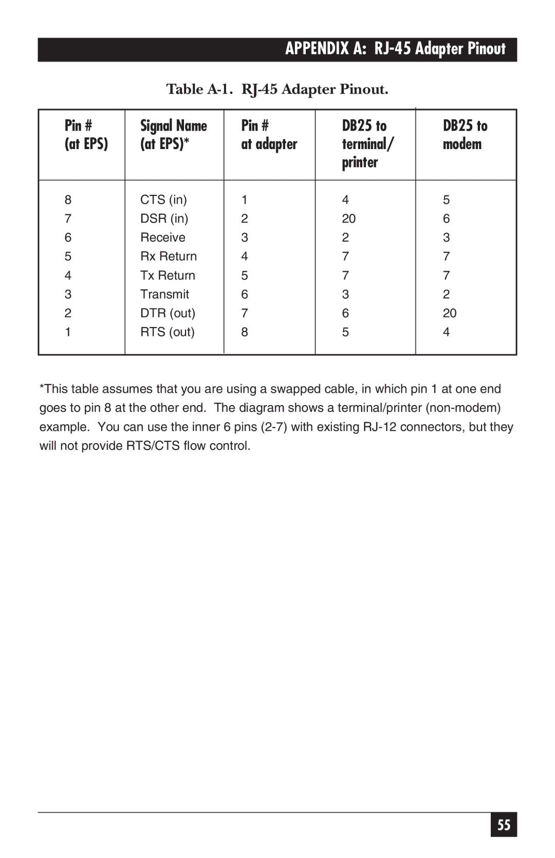
In terms of connectivity, the Black Box LE3700A-R2 offers a range of ports, including USB, Ethernet, and Serial connections, catering to a wide array of devices. This flexibility in connectivity options enhances its usability across different applications, from simple data storage to complex network configurations.
The Black Box LE3700A-R2 is also designed with durability in mind. Its robust construction ensures that it can withstand harsh conditions, making it suitable for use in both indoor and outdoor environments. This reliability is crucial for industries that operate in less-than-ideal conditions, such as construction sites or remote locations.
Overall, the Black Box LE3700A-R2 stands out as an exceptional piece of technology that brings together performance, security, and versatility. Its combination of advanced features and user-centric design makes it a valuable asset for professionals seeking to enhance their operational capabilities and ensure the effective management of data and communications in their respective fields.

