Chapter 3: Installation
3. Installation
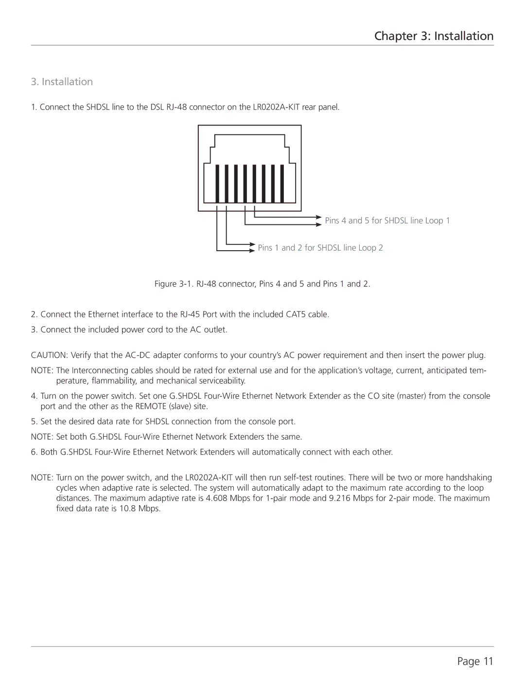
1. Connect the SHDSL line to the DSL
![]() Pins 4 and 5 for SHDSL line Loop 1
Pins 4 and 5 for SHDSL line Loop 1
![]() Pins 1 and 2 for SHDSL line Loop 2
Pins 1 and 2 for SHDSL line Loop 2
Figure 3-1. RJ-48 connector, Pins 4 and 5 and Pins 1 and 2.
2.Connect the Ethernet interface to the RJ-45 Port with the included CAT5 cable.
3.Connect the included power cord to the AC outlet.
CAUTION: Verify that the
NOTE: The Interconnecting cables should be rated for external use and for the application’s voltage, current, anticipated tem- perature, flammability, and mechanical serviceability.
4.Turn on the power switch. Set one G.SHDSL Four-Wire Ethernet Network Extender as the CO site (master) from the console port and the other as the REMOTE (slave) site.
5.Set the desired data rate for SHDSL connection from the console port.
NOTE: Set both G.SHDSL
6. Both G.SHDSL Four-Wire Ethernet Network Extenders will automatically connect with each other.
NOTE: Turn on the power switch, and the
Page 11
