Black Box PCW22A-R4, PCW22A-R3 manual Operation, Asynchronous Device to Synchronous Device

Models: PCW22A-R4 PCW22A-R3

1 33
Download 33 pages 52.54 Kb
Page 16
Image 16

CHAPTER 4: Operation

4.0 Operation

By its nature, a protocol converter must operate differently in each direction, since it is communicating with separate devices. Therefore, its operation will be discussed separately for asynchronous to synchronous operation and for synchronous to asynchronous.

4.1ASYNCHRONOUS DEVICE TO SYNCHRONOUS DEVICE

4.1.1LINE CONTROL

When the A/S-2G is initially connected to an AC power source or reset, the asynchronous device can transmit data.

When the synchronous side has control of the line, a turnaround cannot occur until an “End of Transmission” character has been entered from the controlling device. This character will be an EOT (EBCDIC 37 Hex) on the synchronous side.

4.1.2 ASYNCHRONOUS INPUT DATA FORMAT

The asynchronous side of the A/S-2G is programmed to accept asynchronous data within the following parameters:

1 start bit

7 data bits

1 parity bit (any parity is accepted, but ignored. Parity is user-selectable by SW2, Switches #7 and #8.)

1 or 2 stop bits (user-selectable with SW3, Switch #8)

Half or full duplex (user-selectable with SW2, Switch #3)

75 to 9600 bps (user-selectable by SW1, Switches #1 through #4)

ASCII code


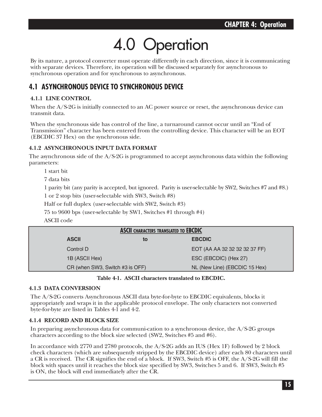
ASCII CHARACTERS TRANSLATED TO EBCDIC

ASCII

to

EBCDIC

Control D


EOT (AA AA 32 32 32 32 37 FF)

1B (ASCII Hex)


ESC (EBCDIC) (Hex 27)

CR (when SW3, Switch #3 is OFF)

NL (New Line) (EBCDIC 15 Hex)


Table 4-1. ASCII characters translated to EBCDIC.

4.1.3 DATA CONVERSION

The A/S-2G converts Asynchronous ASCII data byte-for-byte to EBCDIC equivalents, blocks it appropriately and wraps it in the applicable protocol envelope. The only characters not converted byte-for-byte are listed in Tables 4-1 and 4-2.

4.1.4 RECORD AND BLOCK SIZE

In preparing asynchronous data for communi-cation to a synchronous device, the A/S-2G groups characters according to the block size selected (SW2, Switches #5 and #6).

In accordance with 2770 and 2780 protocols, the A/S-2G adds an IUS (Hex 1F) followed by 2 block check characters (which are subsequently stripped by the EBCDIC device) after each 80 characters until a CR is received. The CR signifies the end of a block. If SW3, Switch #5 is OFF, the A/S-2G will fill the block with spaces until it reaches the block size specified by SW3, Switches 5 and 6. If SW3, Switch #5 is ON, the block will end immediately after the CR.

15

Page 16
Image 16
Black Box PCW22A-R4, PCW22A-R3 manual Operation, Asynchronous Device to Synchronous Device