DUAL- AND QUAD-PORT USB HUBS
Table
Switch | Switch |
|
| Port |
| Description |
|
| |
Setting | Number |
|
|
|
|
|
|
|
|
|
|
|
|
|
|
|
|
|
|
L | 1 |
|
| TX+ | to RX+ | ON | OFF |
| |
L | 1 |
|
| TX- | to RX- | ON | OFF |
| |
T | 1 |
|
| Termination | ON | ON |
| ||
PD | 1 |
| 1K | ON | OFF |
| |||
PU | 1 |
| 1K | ON | OFF |
| |||
L |
| 2 |
| TX+ to RX+ | ON | OFF |
| ||
L |
| 2 |
| TX- to RX- | ON | OFF |
| ||
T | 2 |
|
| Termination | ON | ON |
| ||
PD | 2 |
| 1K | ON | OFF |
| |||
PU | 2 |
| 1K | ON | OFF |
| |||
|
|
|
|
|
|
|
|
|
|
L = Loops TX+ to RX+ or RX- to TX- for
T = Adds a
PU =
PD =
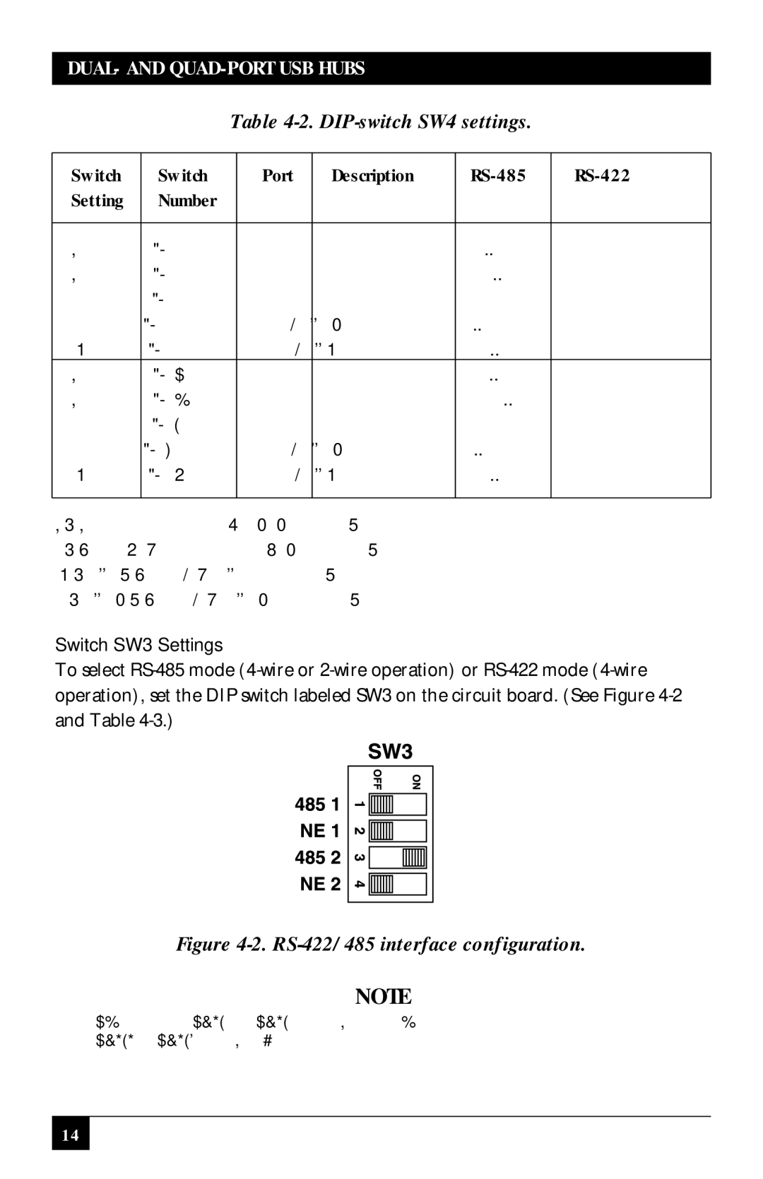
Switch SW3 Settings
To select
Figure 4-2. RS-422/485 interface configuration.
NOTE
Switch positions
14