DUAL- AND QUAD-PORT USB HUBS
Table 4-7 (continued). DIP-switches SW2 and SW4 settings.
Switch | Switch | | Port | Description | RS-485 | RS-422 |
Setting | Number | | | | | | |
| | | | | | | |
PD | SW4-9 | 2 | 1K Pull | -Down | ON | OFF | |
PU | SW4-10 | 2 | 1K Pull-Up | ON | OFF | |
| | | | | | | |
L = Loops TX+ to RX+ for two-wire operation.
T = Adds a 120-ohm termination resistor between RX+ and RX-.
PU = Pull-up. Adds a 1 K-ohm pull-up resistor to RX+.
PD = Pull-down. Adds a 1 K-ohm pull-down resistor to RX-.
Switch SW1 and SW3 Settings
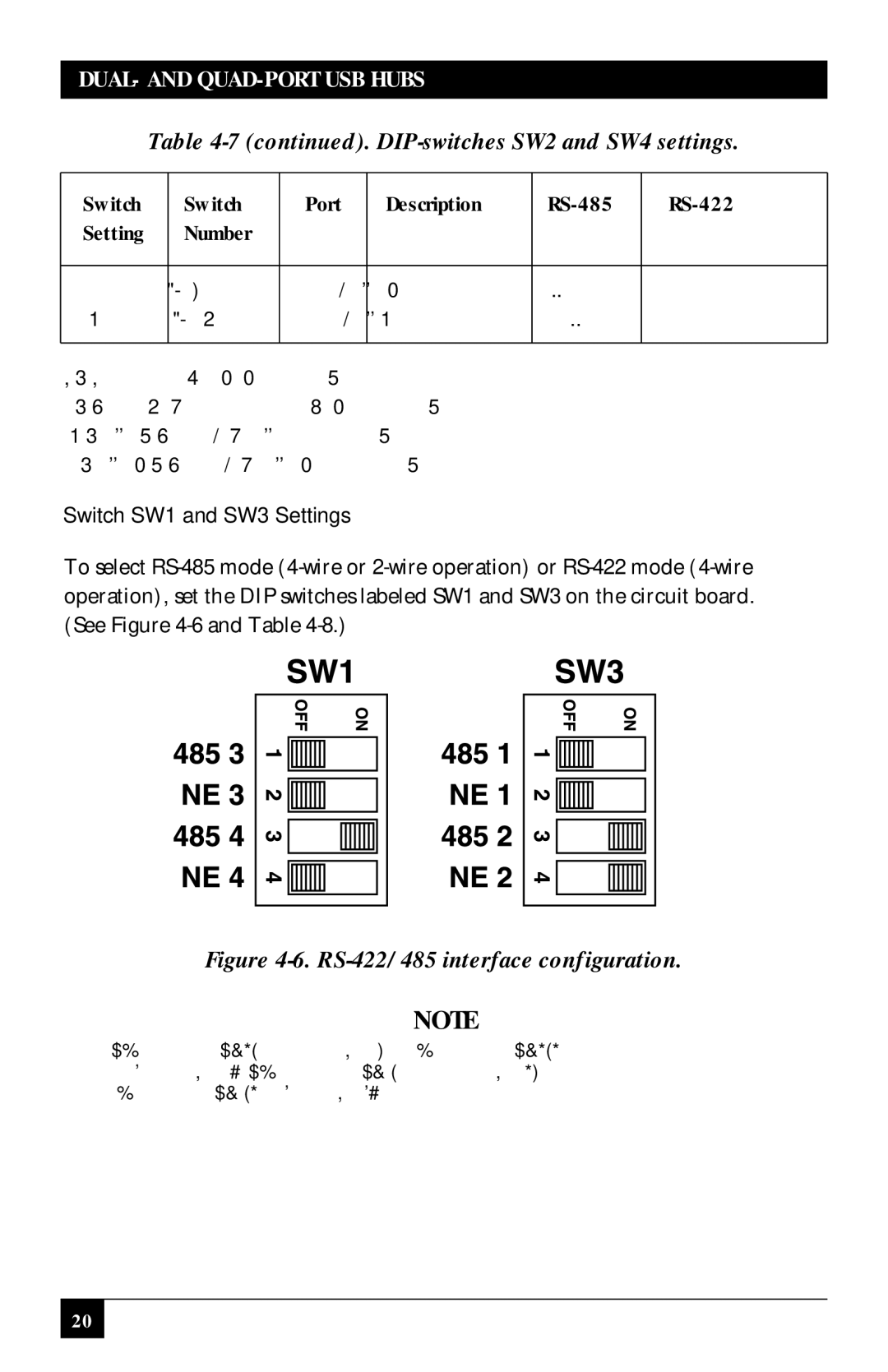
To select RS-485 mode (4-wire or 2-wire operation) or RS-422 mode (4-wire operation), set the DIP switches labeled SW1 and SW3 on the circuit board. (See Figure 4-6 and Table 4-8.)
Figure 4-6. RS-422/485 interface configuration.
NOTE
Switch positions SW3-1 and 2 are for Port 1, and switch positions SW3-3 and 4 are for Port 2. Switch positions SW1-1 and 2 are for Port 3, and switch positions SW1-3 and 4 are for Port 4.

