Black Box SW556AE Installation, 3.1Master and Switched Ports, 1.DB25 connector supported leads

Models: SW556A SW555A SW556AE SW555AE

1 22
Download 22 pages 327 b
Page 11
Image 11
3.Installation

REMOTE MANAGEMENT SWITCH

3.Installation

3.1Master and Switched Ports

Connect the Remote Management Switch’s ports A through D found on the rear of the unit to your RS-232 devices. Each port uses a DB25 subminiature connector and supports the following leads for asynchronous communications.

Table 3-1. DB25 connector supported leads.

Pin

Designation

2

Transmit Data

3

Receive Data

4

Request to Send

5

Clear to Send

6

Data Set Ready

7

Signal Ground

8

Data Carrier Detect

20

Data Terminal Ready

Remote

Management

Switch

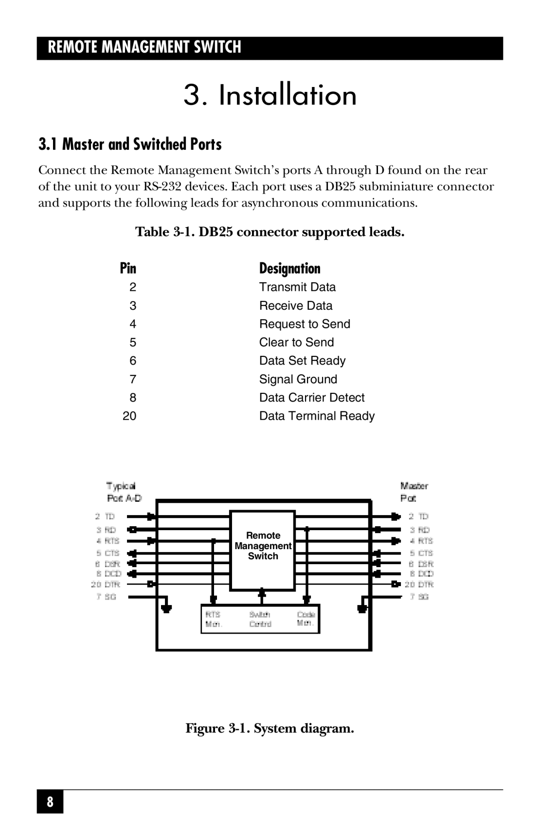
Figure 3-1. System diagram.

8

Page 11
Image 11
Black Box SW556AE, SW555AE Installation, 3.1Master and Switched Ports, 1.DB25 connector supported leads, 1.System diagram