VSC-VPLEX4, VideoPlex4 Video Wall Controller specifications
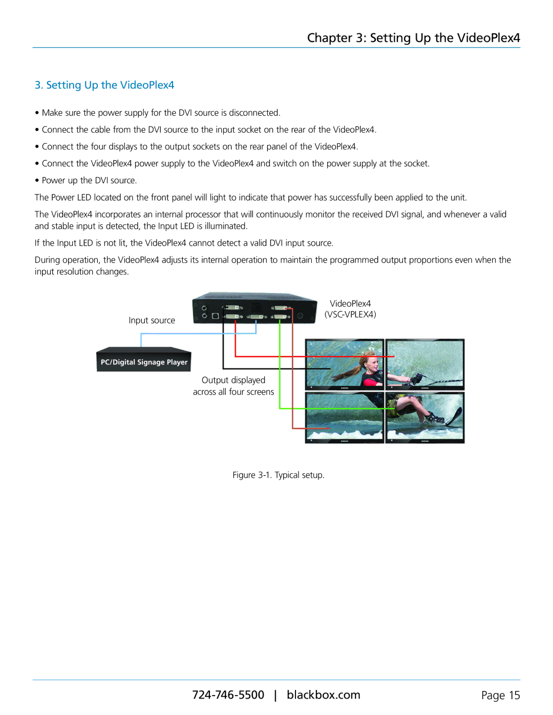
The Black Box VSC-VPLEX4, also known as VideoPlex4, is a sophisticated video wall controller designed to create dynamic and immersive visual displays. This powerful unit is engineered to facilitate the seamless management of multiple video sources, allowing for significant versatility in a variety of environments, such as control rooms, command centers, broadcast studios, and corporate displays.One of the standout features of the VideoPlex4 is its ability to support high-resolution output across various display configurations. With support for up to 4k resolution, users can expect crystal-clear visuals and precise detail, which are critical in applications that require real-time data monitoring or visual analysis. The device can handle various input formats, enabling users to connect an array of source devices, including computers, cameras, and multimedia players.
The VSC-VPLEX4 is built on cutting-edge technology that focuses on enhancing user experience. It comes equipped with an advanced scaling engine that ensures every source is optimized for the video wall display, eliminating issues such as distortion or lag. This technology allows operators to display multiple content types simultaneously, from videos to live feeds, achieving an impressive and cohesive presentation.
The Black Box VideoPlex4 is user-friendly, featuring an intuitive interface that simplifies the control of complex video wall setups. The control software is designed for flexibility, offering customizable layouts and the ability to interactively manage content through drag-and-drop functionality. This ensures that even non-technical users can operate the system with confidence.
Additionally, the VSC-VPLEX4 supports various output types, including HDMI, DVI, and DisplayPort, ensuring compatibility with a wide range of display technologies. Built-in multi-view capabilities allow for the simultaneous display of multiple sources on a single screen, which is ideal for environments that require real-time monitoring of various inputs.
The robust design of the VideoPlex4 ensures reliability in demanding environments. Its sturdy construction is complemented by features such as redundant power supplies, which provide an additional layer of security to keep operations running smoothly.
In conclusion, the Black Box VSC-VPLEX4 VideoPlex4 Video Wall Controller is an essential tool for professionals who demand high-quality visuals and reliable performance. With its advanced features and technologies, it stands out as a premier choice for creating stunning video wall experiences in any setting. Whether for control rooms or public exhibitions, VideoPlex4 meets the needs of modern display applications with excellence.

