Installation en 11 | |
|
|
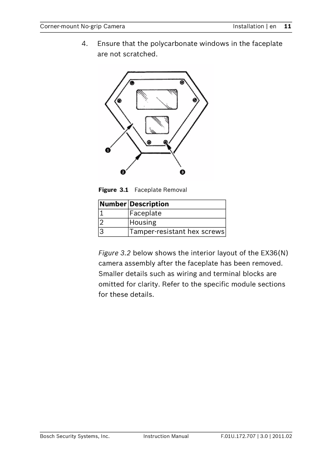
4.Ensure that the polycarbonate windows in the faceplate are not scratched.
Figure 3.1 Faceplate Removal
Number Description
1Faceplate
2Housing
3
Figure 3.2 below shows the interior layout of the EX36(N) camera assembly after the faceplate has been removed. Smaller details such as wiring and terminal blocks are omitted for clarity. Refer to the specific module sections for these details.
Bosch Security Systems, Inc. | Instruction Manual | F.01U.172.707 3.0 2011.02 |