12 en Installation | |
|
|
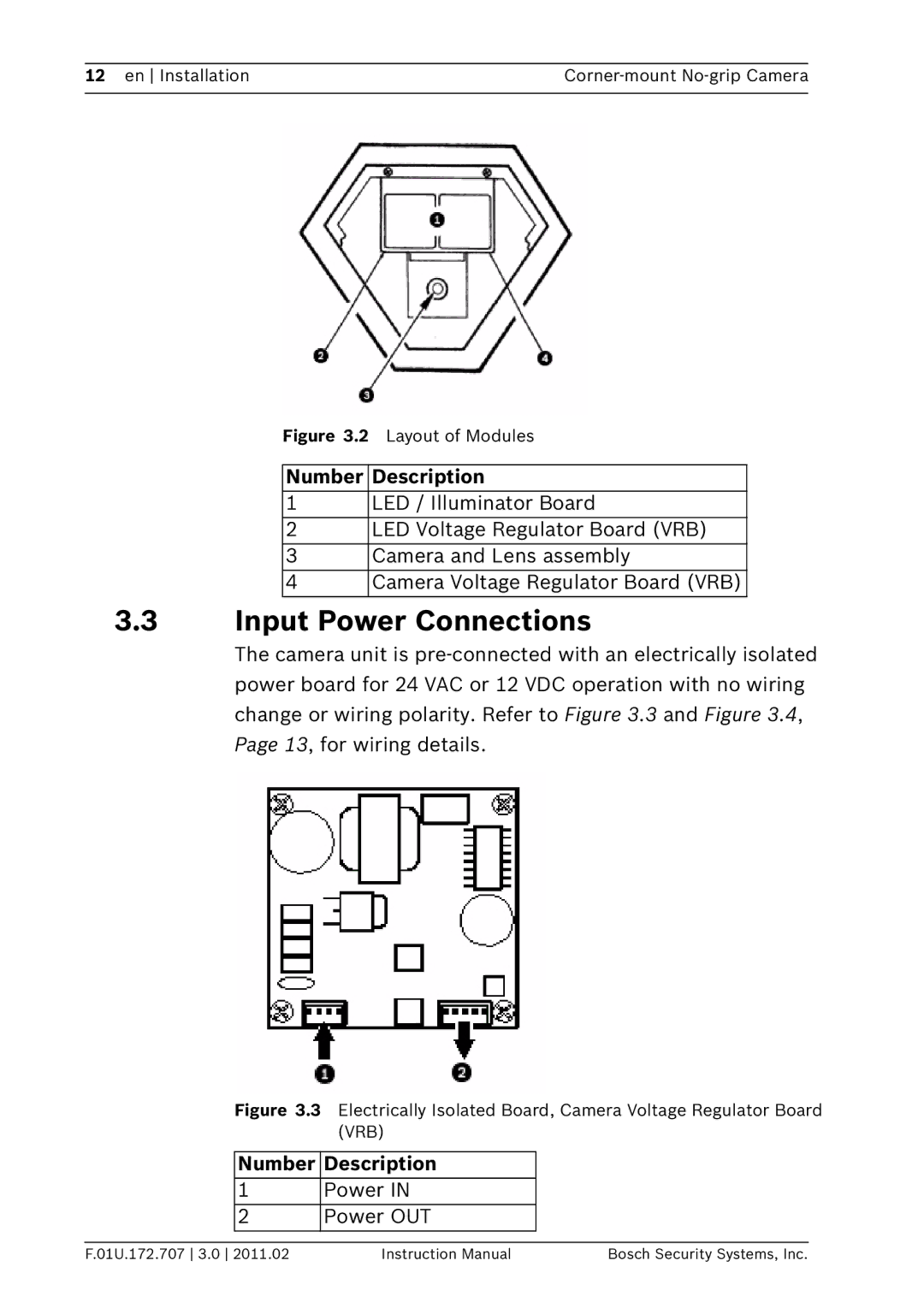
Figure 3.2 Layout of Modules
Number Description
1LED / Illuminator Board
2LED Voltage Regulator Board (VRB)
3 Camera and Lens assembly
4 Camera Voltage Regulator Board (VRB)
3.3Input Power Connections
The camera unit is
Figure 3.3 Electrically Isolated Board, Camera Voltage Regulator Board (VRB)
Number Description
1Power IN
2 Power OUT
F.01U.172.707 3.0 2011.02 | Instruction Manual | Bosch Security Systems, Inc. |