DinionHD 1080p HDR | Installation en 23 |
|
|
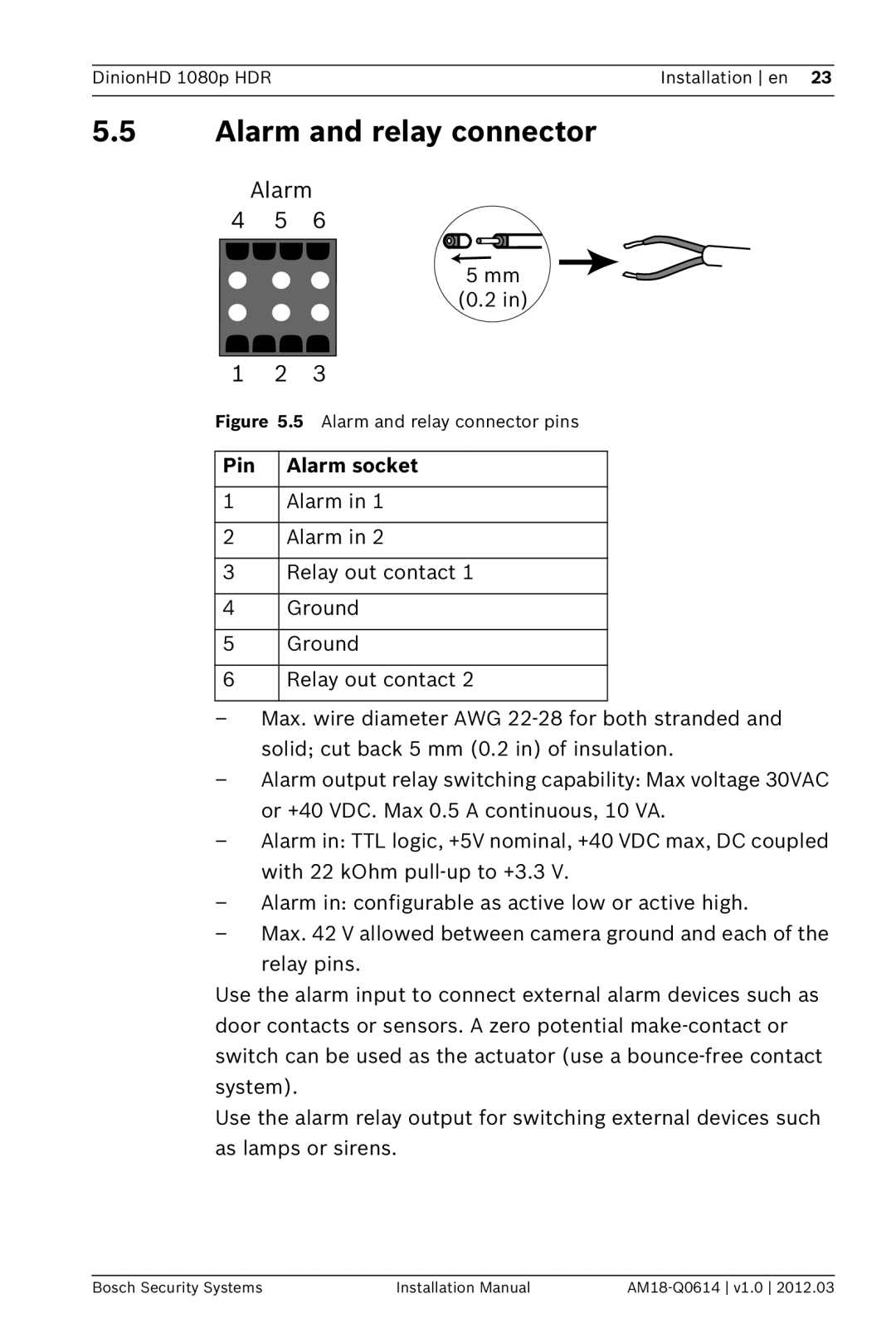
5.5Alarm and relay connector
Alarm
4 | 5 | 6 |
|
|
|
|
| |
|
|
|
|
|
|
|
|
|
|
|
| 5 mm |
|
| |||
|
|
|
|
| ||||
|
|
| (0.2 in) | |||||
1 | 2 | 3 |
|
|
|
|
| |
Figure 5.5 | Alarm and relay connector pins | |||||||
|
|
|
|
|
|
|
| |
Pin |
| Alarm socket | ||||||
|
|
|
|
|
|
|
| |
1 |
| Alarm in 1 | ||||||
|
|
|
|
|
|
|
| |
2 |
| Alarm in 2 | ||||||
|
|
|
|
|
|
|
| |
3 |
| Relay out contact 1 | ||||||
|
|
|
|
|
|
|
| |
4 |
| Ground | ||||||
|
|
|
|
|
|
|
| |
5 |
| Ground | ||||||
|
|
|
|
|
|
|
| |
6 |
| Relay out contact 2 | ||||||
|
|
|
|
|
|
|
|
|
–Max. wire diameter AWG
–Alarm output relay switching capability: Max voltage 30VAC or +40 VDC. Max 0.5 A continuous, 10 VA.
–Alarm in: TTL logic, +5V nominal, +40 VDC max, DC coupled with 22 kOhm
–Alarm in: configurable as active low or active high.
–Max. 42 V allowed between camera ground and each of the
relay pins.
Use the alarm input to connect external alarm devices such as door contacts or sensors. A zero potential
Use the alarm relay output for switching external devices such as lamps or sirens.
Bosch Security Systems | Installation Manual |