To level stand
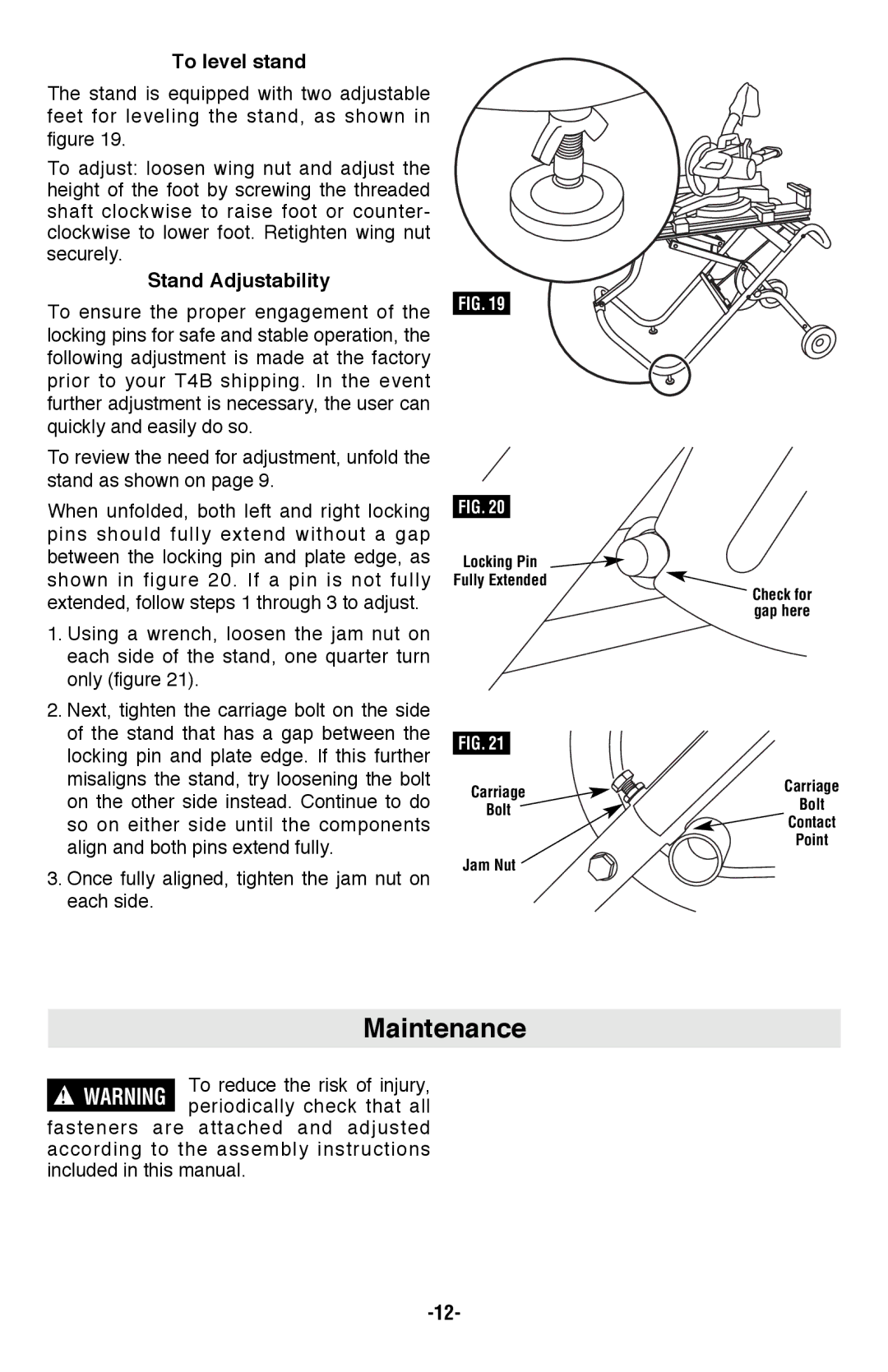
The stand is equipped with two adjustable feet for leveling the stand, as shown in figure 19.
To adjust: loosen wing nut and adjust the height of the foot by screwing the threaded shaft clockwise to raise foot or counter- clockwise to lower foot. Retighten wing nut securely.
Stand Adjustability
To ensure the proper engagement of the locking pins for safe and stable operation, the following adjustment is made at the factory prior to your T4B shipping. In the event further adjustment is necessary, the user can quickly and easily do so.
To review the need for adjustment, unfold the stand as shown on page 9.
When unfolded, both left and right locking pins should fully extend without a gap between the locking pin and plate edge, as shown in figure 20. If a pin is not fully extended, follow steps 1 through 3 to adjust.
1.Using a wrench, loosen the jam nut on each side of the stand, one quarter turn only (figure 21).
2.Next, tighten the carriage bolt on the side of the stand that has a gap between the locking pin and plate edge. If this further misaligns the stand, try loosening the bolt on the other side instead. Continue to do so on either side until the components align and both pins extend fully.
3.Once fully aligned, tighten the jam nut on each side.
FIG. 19
FIG. 20
Locking Pin
Fully Extended
FIG. 21
Carriage
Bolt
Jam Nut
Check for gap here
Carriage
Bolt
![]() Contact
Contact
Point
Maintenance
To reduce the risk of injury, ! WARNING periodically check that all
fasteners are attached and adjusted according to the assembly instructions included in this manual.