System Installation Instructions
Figure 8
A
3
Figure 9
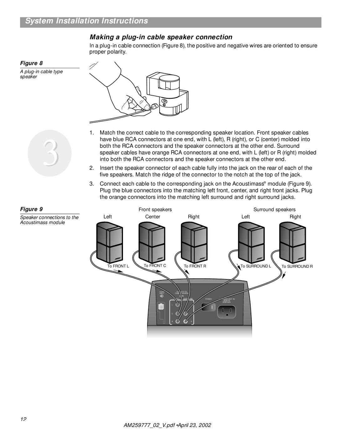
Speaker connections to the Acoustimass module
Making a plug-in cable speaker connection
In a
1.Match the correct cable to the corresponding speaker location. Front speaker cables have blue RCA connectors at one end, with L (left), R (right), or C (center) molded into both the RCA connectors and the speaker connectors at the other end. Surround speaker cables have orange RCA connectors at one end, with L (left) or R (right) molded into both the RCA connectors and the speaker connectors at the other end.
2.Insert the speaker connector of each cable fully into the jack on the rear of each of the five speakers. Match the ridge of the connector to the notch at the top of the jack.
3.Connect each cable to the corresponding jack on the Acoustimass® module (Figure 9). Plug the blue connectors into the matching left front, center, and right front jacks. Plug the orange connectors into the matching left surround and right surround jacks.
| Front speakers |
|
| Surround speakers |
Left | Center | Right | Left | Right |
To FRONT L | To FRONT C | To FRONT R | To SURROUND L | To SURROUND R | |
| AUDIO | OUTPUTS TO |
|
|
|
| INPUT | CUBE SPEAKERS |
|
|
|
|
| FRONT SURROUND | POWER |
| |
|
|
|
| 50/60 Hz |
|
|
|
|
| 350W MAX. |
|
| L |
|
|
|
|
| C | L |
|
|
|
| R | R |
|
|
|
12
AM259777_02_V.pdf • April 23, 2002