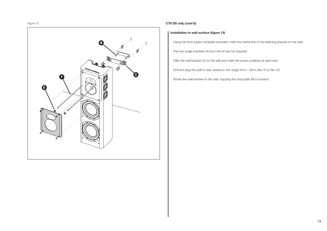
Figure 13 | CT8 DS only (cont’d) |
Installation to wall surface (figure 13)
Using the front aspect template provided, mark the centre line of the retaining bracket on the wall.
The two angle brackets (A) from the kit are not required.
Offer the wall bracket (C) to the wall and mark the screw positions at each end.
Drill and plug the wall to take screws in the range 5mm – 6mm (No.10 to No.12)
Screw the wall bracket to the wall, trapping the stud plate (B) in position.
13