Figure 14 | CT8 DS only (cont’d) |
Continue for all cases
Connect the signal and trigger cables to the speaker.
Using the Allen key provided, remove the aluminium facing plate on the front of the speaker, taking care that the tweeter protection cover remains in position.
Fit the guide tubes (F) into the two through holes.
Offer the speaker into position, ensuring that the guide tubes (F) locate over the studs of the bracket (B).
When the speaker is fully in position hard against the wall bracket, withdraw the guide tubes.
Using a 1⁄4 inch socket drive with extension and the 13mm socket provided, fit the two flanged nuts (E) onto the threaded studs and tighten. If the socket drive does not have a nut retaining feature, we recommend the use of a small piece of Bostik®
Replace the facing plate on the front of the speaker and remove the tweeter protection cover.
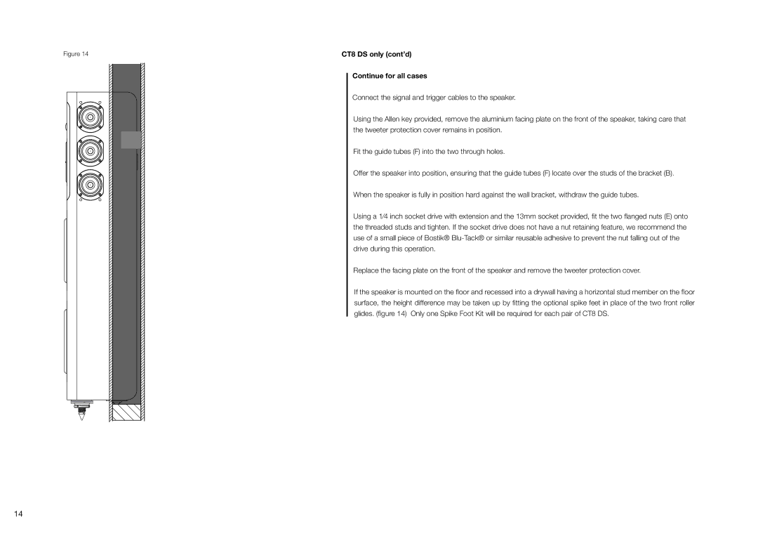
If the speaker is mounted on the floor and recessed into a drywall having a horizontal stud member on the floor surface, the height difference may be taken up by fitting the optional spike feet in place of the two front roller glides. (figure 14) Only one Spike Foot Kit will be required for each pair of CT8 DS.
14