SERVICE PROCEDURE
Inner Door/Gasket Removal, Inspection
Replacement and Reinstallation
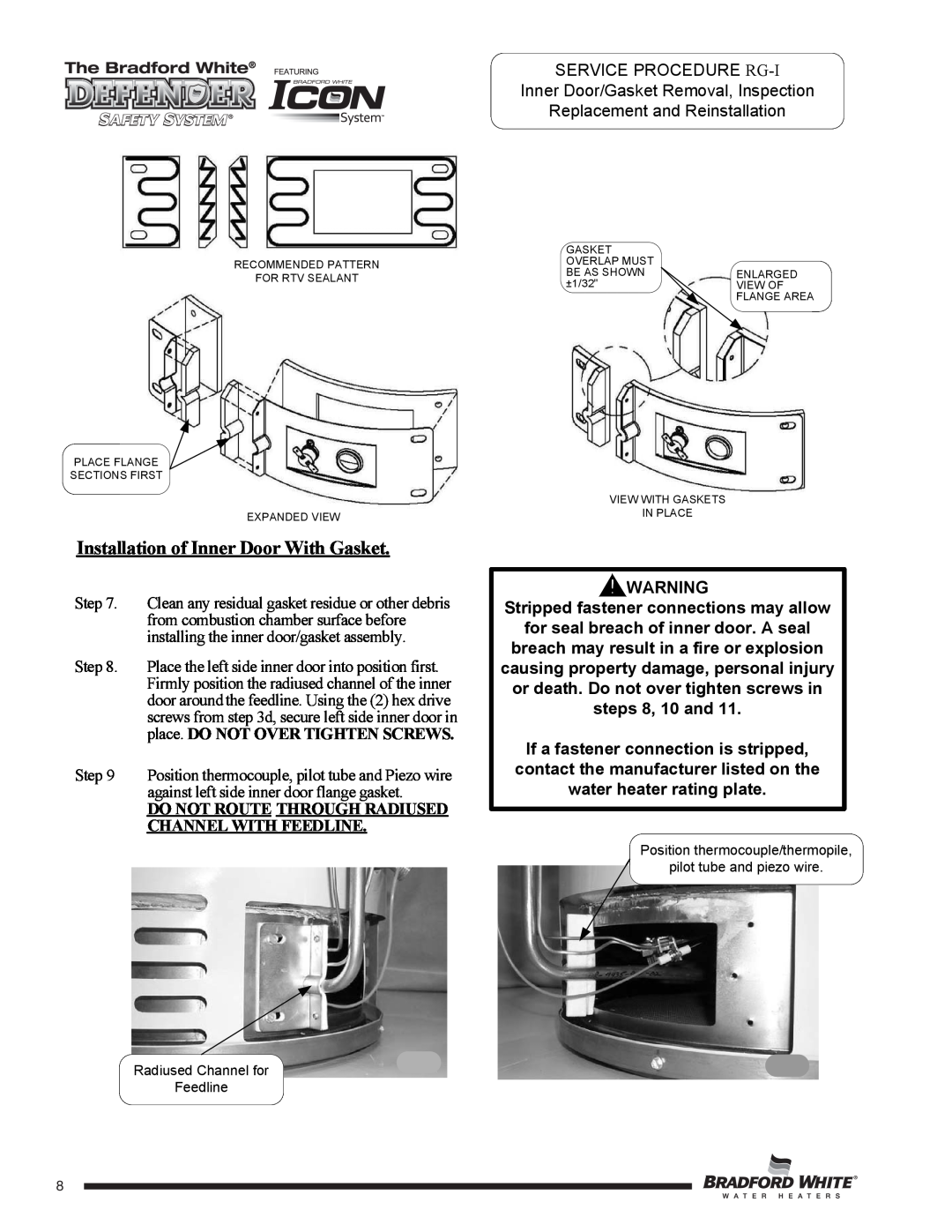
RECOMMENDED PATTERN
FOR RTV SEALANT
PLACE FLANGE
SECTIONS FIRST
EXPANDED VIEW
Installation of Inner Door With Gasket.
Step 7. Clean any residual gasket residue or other debris from combustion chamber surface before installing the inner door/gasket assembly.
Step 8. Place the left side inner door into position first. Firmly position the radiused channel of the inner door around the feedline. Using the (2) hex drive screws from step 3d, secure left side inner door in place. DO NOT OVER TIGHTEN SCREWS.
Step 9 Position thermocouple, pilot tube and Piezo wire against left side inner door flange gasket.
DO NOT ROUTE THROUGH RADIUSED CHANNEL WITH FEEDLINE.
Radiused Channel for
Feedline
8
GASKET |
|
OVERLAP MUST |
|
BE AS SHOWN | ENLARGED |
±1/32" | VIEW OF |
| FLANGE AREA |
VIEW WITH GASKETS
IN PLACE
![]()
![]() WARNING
WARNING
Stripped fastener connections may allow
for seal breach of inner door. A seal breach may result in a fire or explosion causing property damage, personal injury or death. Do not over tighten screws in steps 8, 10 and 11.
If a fastener connection is stripped, contact the manufacturer listed on the water heater rating plate.
Position thermocouple/thermopile,
pilot tube and piezo wire.
88