Brute Mini Hydronic Boiler | Page 21 |
|
|
6.3 Grounding
![]() WARNING
WARNING
The boiler must be electrically grounded in accordance with the requirements of the authority having jurisdiction or, in the absence of such requirements, with the latest edition of the National Electrical Code, ANSI/NFPA 70, in the U.S. and with latest edition of CSA C22.1 Canadian Electrical Code, Part 1, in Canada. Do not rely on the gas or water piping to ground the metal parts of the boiler. Plastic pipe or dielectric unions may isolate the boiler electrically. Service and maintenance personnel who work on or around the boiler may be standing on wet floors and could be electrocuted by an ungrounded boiler.
 AVERTISSEMENT
La chaudière doit être mise à la terre selon les exigences officielles locales ou, en l’absence de toute instruction officelle, l’installation doit être conforme au National Electrical Code, ANSI/NFPA 70, aux
6.4 Auxiliary Devices
6.4.1 Flow Switch
SECTION 7.
Operating Instructions
7.1 Normal Operation
The Brute Mini BJVS and BJVT boilers are capable of automatic operation based on a call for heat at present temperatures. The boiler has an internal safety system which allows operation in a variety of conditions and prevents operation when certain adverse conditions are encountered.
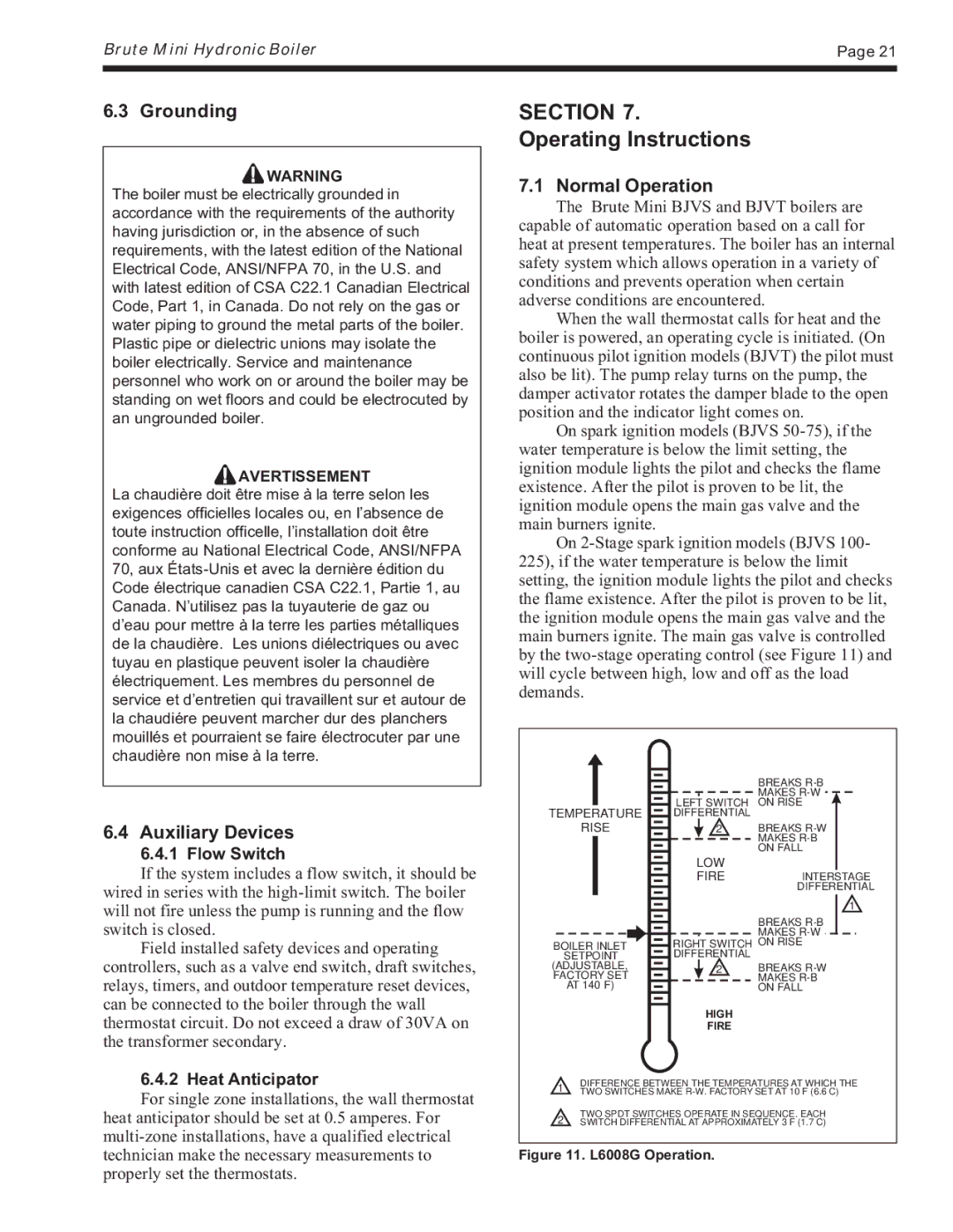
When the wall thermostat calls for heat and the boiler is powered, an operating cycle is initiated. (On continuous pilot ignition models (BJVT) the pilot must also be lit). The pump relay turns on the pump, the damper activator rotates the damper blade to the open position and the indicator light comes on.
On spark ignition models (BJVS
On
|
|
|
|
|
| BREAKS |
|
|
|
|
|
| MAKES |
|
|
|
|
|
| |
|
|
|
| LEFT SWITCH | ON RISE | |
|
|
|
| |||
TEMPERATURE |
|
|
| DIFFERENTIAL |
| |
|
|
|
| |||
RISE |
|
|
|
| 2 | BREAKS |
|
|
| ||||
|
|
|
|
|
| MAKES |
|
|
|
|
|
| |
|
|
|
|
|
| ON FALL |
If the system includes a flow switch, it should be wired in series with the
Field installed safety devices and operating
controllers, such as a valve end switch, draft switches, relays, timers, and outdoor temperature reset devices, can be connected to the boiler through the wall thermostat circuit. Do not exceed a draw of 30VA on the transformer secondary.
BOILER INLET
SETPOINT
(ADJUSTABLE, FACTORY SET AT 140°F)
LOW
FIREINTERSTAGE DIFFERENTIAL
1
BREAKS
MAKES
RIGHT SWITCH ON RISE DIFFERENTIAL
2BREAKS
HIGH
FIRE
6.4.2 Heat Anticipator
For single zone installations, the wall thermostat heat anticipator should be set at 0.5 amperes. For
DIFFERENCE BETWEEN THE TEMPERATURES AT WHICH THE
1TWO SWITCHES MAKE
TWO SPDT SWITCHES OPERATE IN SEQUENCE. EACH
2SWITCH DIFFERENTIAL AT APPROXIMATELY 3°F (1.7°C)