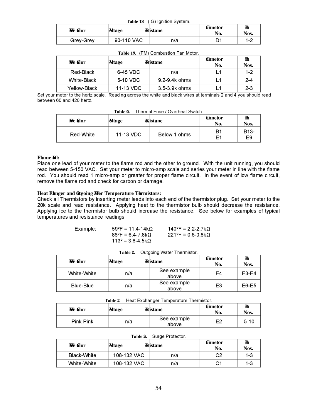
| Table 18. (IG) Ignition System. |
|
| ||
Wire Color | Voltage | Resistance | Connector | Pin | |
No. | Nos. | ||||
|
|
| |||
n/a | D1 | ||||
| Table 19. (FM) Combustion Fan Motor. |
|
| ||
Wire Color | Voltage | Resistance | Connector | Pin | |
No. | Nos. | ||||
|
|
| |||
n/a | L1 | ||||
L1 | |||||
L1 | |||||
Set your meter to the hertz scale. Reading across the white and black wires at terminals 2 and 4 you should read between 60 and 420 hertz.
| Table 20. Thermal Fuse / Overheat Switch. |
|
| ||
Wire Color | Voltage | Resistance |
| Connector | Pin |
| No. | Nos. | |||
|
|
|
| ||
Below 1 ohms |
| B1 | B13- | ||
| E1 | E9 | |||
|
|
|
| ||
|
|
|
|
|
|
Flame Rod:
Place one lead of your meter to the flame rod and the other to ground. With the unit running, you should read between
Heat Exchanger and Outgoing Water Temperature Thermistors:
Check all Thermistors by inserting meter leads into each end of the thermistor plug. Set your meter to the 20k scale and read resistance. Applying heat to the thermistor bulb should decrease the resistance. Applying ice to the thermistor bulb should increase the resistance. See below for examples of typical temperatures and resistance readings.
Example: |
| 59ºF = | 140ºF = |
| ||
|
| 86ºF = | 221ºF = |
| ||
|
| 113º = |
|
|
| |
|
| Table 21. Outgoing Water Thermistor. |
|
| ||
Wire Color |
| Voltage |
| Resistance | Connector | Pin |
|
| No. | Nos. | |||
|
|
|
|
| ||
| n/a |
| See example | E4 | ||
|
| above | ||||
|
|
|
|
|
| |
| n/a |
| See example | E3 | ||
|
| above | ||||
|
|
|
|
|
| |
| Table 22. Heat Exchanger Temperature Thermistor. |
| ||||
Wire Color |
| Voltage |
| Resistance | Connector | Pin |
|
| No. | Nos. | |||
|
|
|
|
| ||
| n/a |
| See example | E2 | ||
|
| above | ||||
|
|
|
|
|
| |
|
| Table 23. Surge Protector. |
|
| ||
Wire Color |
| Voltage |
| Resistance | Connector | Pin |
|
| No. | Nos. | |||
|
|
|
|
| ||
|
| n/a | C2 | |||
|
| n/a | C1 | |||
54
