| Express® Lavatory System |
Installation Instructions - For Service Only | |
|
|
Installation Instructions continued . . .
Step 4: Connecting supply
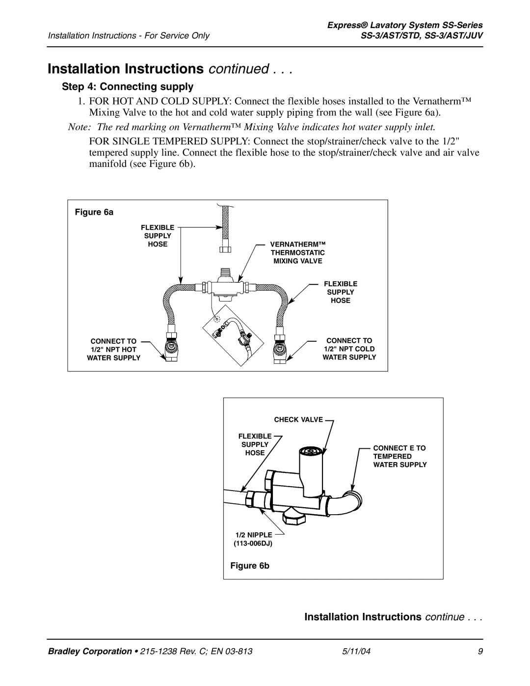
1.FOR HOT AND COLD SUPPLY: Connect the flexible hoses installed to the Vernatherm™ Mixing Valve to the hot and cold water supply piping from the wall (see Figure 6a).
Note: The red marking on Vernatherm™ Mixing Valve indicates hot water supply inlet.
FOR SINGLE TEMPERED SUPPLY: Connect the stop/strainer/check valve to the 1/2" tempered supply line. Connect the flexible hose to the stop/strainer/check valve and air valve manifold (see Figure 6b).
Figure 6a
FLEXIBLE
SUPPLY
HOSE
VERNATHERM™
THERMOSTATIC
MIXING VALVE
FLEXIBLE
SUPPLY
HOSE
CONNECT TO |
|
|
|
|
| CONNECT TO |
|
|
| ||||
1/2" NPT HOT |
|
| 1/2" NPT COLD | |||
WATER SUPPLY |
|
| WATER SUPPLY | |||
|
|
|
|
|
|
|
FLEXIBLE | CHECK VALVE |
|
| ||
| |||||
|
|
|
|
| |
|
|
|
|
| |
SUPPLY |
|
|
|
|
|
|
|
|
| CONNECT E TO | |
HOSE |
|
|
|
| |
|
|
|
| TEMPERED | |
|
|
|
|
| |
|
|
|
|
| WATER SUPPLY |
|
|
|
|
|
|
1/2 NIPPLE
Figure 6b
Installation Instructions continue . . .
Bradley Corporation • | 5/11/04 | 9 |
